Resistivity imaging provides detailed subsurface electrical property maps, making it ideal for identifying variations in soil and rock layers, moisture content, and fractures. Ground penetrating radar (GPR) offers high-resolution imaging of shallow subsurface features by detecting reflected electromagnetic waves, which is effective for locating buried objects and voids. Combining both techniques enhances geological engineering investigations by leveraging resistivity's depth penetration and GPR's spatial detail.
Table of Comparison
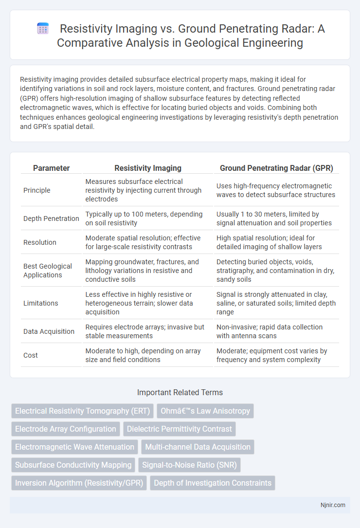
| Parameter | Resistivity Imaging | Ground Penetrating Radar (GPR) |
|---|---|---|
| Principle | Measures subsurface electrical resistivity by injecting current through electrodes | Uses high-frequency electromagnetic waves to detect subsurface structures |
| Depth Penetration | Typically up to 100 meters, depending on soil resistivity | Usually 1 to 30 meters, limited by signal attenuation and soil properties |
| Resolution | Moderate spatial resolution; effective for large-scale resistivity contrasts | High spatial resolution; ideal for detailed imaging of shallow layers |
| Best Geological Applications | Mapping groundwater, fractures, and lithology variations in resistive and conductive soils | Detecting buried objects, voids, stratigraphy, and contamination in dry, sandy soils |
| Limitations | Less effective in highly resistive or heterogeneous terrain; slower data acquisition | Signal is strongly attenuated in clay, saline, or saturated soils; limited depth range |
| Data Acquisition | Requires electrode arrays; invasive but stable measurements | Non-invasive; rapid data collection with antenna scans |
| Cost | Moderate to high, depending on array size and field conditions | Moderate; equipment cost varies by frequency and system complexity |
Introduction to Subsurface Investigation Methods
Resistivity imaging measures the electrical resistance of subsurface materials to identify variations in lithology, moisture content, and contaminants, providing detailed 2D or 3D images of underground structures. Ground penetrating radar (GPR) employs high-frequency electromagnetic waves to detect and map subsurface features by reflecting signals off different material boundaries with varying dielectric constants. Both methods are crucial in subsurface investigation, with resistivity imaging excelling in differentiating conductive and resistive layers, while GPR offers high-resolution detection of shallow objects and stratigraphy.
Principles of Resistivity Imaging
Resistivity imaging measures subsurface electrical resistivity by injecting current into the ground through electrodes and recording potential differences, revealing variations in soil and rock conductivity. This method exploits the principle that different materials conduct electricity differently due to factors like moisture content, porosity, and mineral composition. Unlike ground penetrating radar, which uses electromagnetic waves to detect subsurface features, resistivity imaging provides detailed information about the electrical properties of underground formations, making it effective for detecting groundwater, voids, and contamination plumes.
Fundamentals of Ground Penetrating Radar (GPR)
Ground Penetrating Radar (GPR) operates by transmitting high-frequency electromagnetic waves into the subsurface and analyzing the reflected signals from material boundaries to create detailed images. Unlike resistivity imaging, which measures subsurface electrical resistance by injecting current through electrodes, GPR detects variations in dielectric permittivity and moisture content, offering higher resolution for shallow investigations. GPR is especially effective in delineating stratigraphy, utilities, and voids in dry, sandy, or rocky soils, whereas resistivity imaging excels in differentiating layers based on resistivity contrasts in moist or clay-rich environments.
Data Acquisition Techniques: Resistivity vs. GPR
Resistivity imaging relies on the injection of electrical currents into the ground using electrodes and measures the resultant voltage differences to map subsurface resistivity variations, requiring direct contact with the soil. Ground Penetrating Radar (GPR) employs high-frequency electromagnetic waves emitted by a transmitting antenna, recording the reflected signals from buried objects or layers without soil contact, enabling faster data acquisition over large areas. Resistivity acquisition is more sensitive to moisture content and requires careful electrode placement, while GPR data quality depends heavily on antenna frequency, soil conductivity, and surface conditions.
Resolution and Depth of Investigation
Resistivity imaging offers greater depth of investigation, typically reaching tens to hundreds of meters, making it suitable for detecting subsurface features at significant depths. Ground penetrating radar (GPR) provides higher resolution, often on the order of centimeters, enabling detailed imaging of shallow subsurface structures up to a few meters deep. The choice between resistivity imaging and GPR depends on the required balance between penetration depth and spatial resolution for specific geophysical applications.
Geological Applications and Limitations
Resistivity imaging excels in mapping subsurface lithology by measuring electrical resistance variations, providing detailed information on soil moisture, porosity, and mineral content, making it ideal for geological applications like aquifer delineation and contaminant mapping. Ground penetrating radar (GPR) leverages electromagnetic wave reflections to detect subsurface structures and stratigraphy but faces limitations in clay-rich or saline environments where signal attenuation reduces effectiveness. Both methods complement each other; resistivity offers deeper penetration in conductive soils, while GPR provides high-resolution imaging in dry, sandy, or rocky terrains.
Interpretation and Data Processing Differences
Resistivity imaging relies on measuring subsurface electrical resistance variations, requiring inversion algorithms to interpret resistivity contrasts associated with different materials, often producing continuous 2D or 3D resistivity models. Ground penetrating radar (GPR) captures reflected electromagnetic waves, necessitating specialized signal processing techniques like migration, filtering, and amplitude analysis to convert time-domain radargrams into spatial subsurface images. Resistivity inversion is generally computationally intensive but yields quantitative resistivity values, whereas GPR interpretation focuses more on identifying reflection patterns and dielectric contrasts to delineate subsurface features.
Environmental Conditions Affecting Results
Resistivity imaging performance depends heavily on soil moisture, temperature, and ionic content, as high conductivity materials like clays can reduce data quality. Ground penetrating radar (GPR) effectiveness varies with soil texture, moisture content, and the presence of electrically conductive minerals, where wet or clay-rich soils attenuate radar signals. Both methods require careful consideration of environmental conditions to optimize subsurface imaging accuracy in geophysical surveys.
Cost Efficiency and Operational Considerations
Resistivity imaging offers lower equipment and operational costs compared to ground penetrating radar (GPR), making it cost-efficient for large-scale subsurface investigations. Its equipment requires less specialized training, reducing labor expenses and allowing for easier deployment in varied soil conditions. GPR, while providing higher resolution data, demands significant investment in technology and expert interpretation, increasing overall project costs and operational complexity.
Choosing the Right Method for Geological Engineering Projects
Resistivity imaging excels in delineating subsurface features by measuring electrical resistance variations, making it ideal for identifying groundwater, clay layers, and bedrock boundaries in geological engineering projects. Ground penetrating radar (GPR) provides high-resolution images of shallow subsurface structures by detecting reflected electromagnetic waves, especially effective in sandy or dry soils with minimal clay content. Selecting the appropriate method depends on soil type, depth of investigation, required resolution, and project goals--resistivity suits deeper or clay-rich environments, while GPR is preferred for detailed shallow surveys in non-conductive materials.
Electrical Resistivity Tomography (ERT)
Electrical Resistivity Tomography (ERT) provides higher-resolution subsurface imaging by measuring soil resistivity variations compared to Ground Penetrating Radar (GPR), which is more sensitive to dielectric contrasts.
Ohm’s Law Anisotropy
Resistivity imaging employs Ohm's Law to measure subsurface electrical anisotropy by detecting variations in resistivity, whereas ground penetrating radar relies on electromagnetic wave propagation and dielectric permittivity contrasts, making resistivity more sensitive to anisotropic conductive properties.
Electrode Array Configuration
Electrode array configuration in resistivity imaging crucially influences data resolution and depth penetration, offering more customizable subsurface electrical property mapping compared to the fixed antenna spacing in ground penetrating radar systems.
Dielectric Permittivity Contrast
Resistivity imaging measures subsurface electrical resistivity contrasts while ground penetrating radar detects dielectric permittivity contrasts, making GPR more sensitive to variations in material moisture content and composition.
Electromagnetic Wave Attenuation
Resistivity imaging measures subsurface electrical resistivity with minimal electromagnetic wave attenuation, while ground penetrating radar (GPR) signals experience significant attenuation in conductive materials, limiting depth penetration and resolution.
Multi-channel Data Acquisition
Multi-channel data acquisition in resistivity imaging enables simultaneous collection of multiple electrode measurements, enhancing subsurface resolution and depth penetration compared to ground penetrating radar's single-channel or limited multi-channel capabilities.
Subsurface Conductivity Mapping
Resistivity imaging provides detailed subsurface conductivity mapping by measuring electrical resistance variations, offering higher resolution of conductive materials compared to ground penetrating radar, which relies on electromagnetic wave reflections.
Signal-to-Noise Ratio (SNR)
Resistivity imaging typically offers a higher signal-to-noise ratio (SNR) than ground penetrating radar (GPR) in conductive soils, enhancing subsurface feature detection accuracy.
Inversion Algorithm (Resistivity/GPR)
Resistivity imaging uses inversion algorithms that solve nonlinear optimization problems to reconstruct subsurface resistivity distribution, while ground penetrating radar (GPR) employs inversion techniques based on electromagnetic wave propagation models to map dielectric permittivity variations underground.
Depth of Investigation Constraints
Resistivity imaging typically achieves greater depth of investigation, ranging from tens to hundreds of meters depending on electrode spacing and ground conditions, whereas ground penetrating radar is limited to shallower depths, generally up to 30 meters, constrained by signal attenuation in conductive materials.
resistivity imaging vs ground penetrating radar Infographic