I2C and SPI are widely used communication protocols in computer engineering for connecting microcontrollers and peripheral devices. I2C uses a two-wire interface allowing multiple devices to share the same bus, making it ideal for simpler, low-speed communication and reducing wiring complexity. SPI offers higher data transfer rates with a four-wire interface, providing full-duplex communication and better performance for applications requiring fast and reliable data exchange.
Table of Comparison
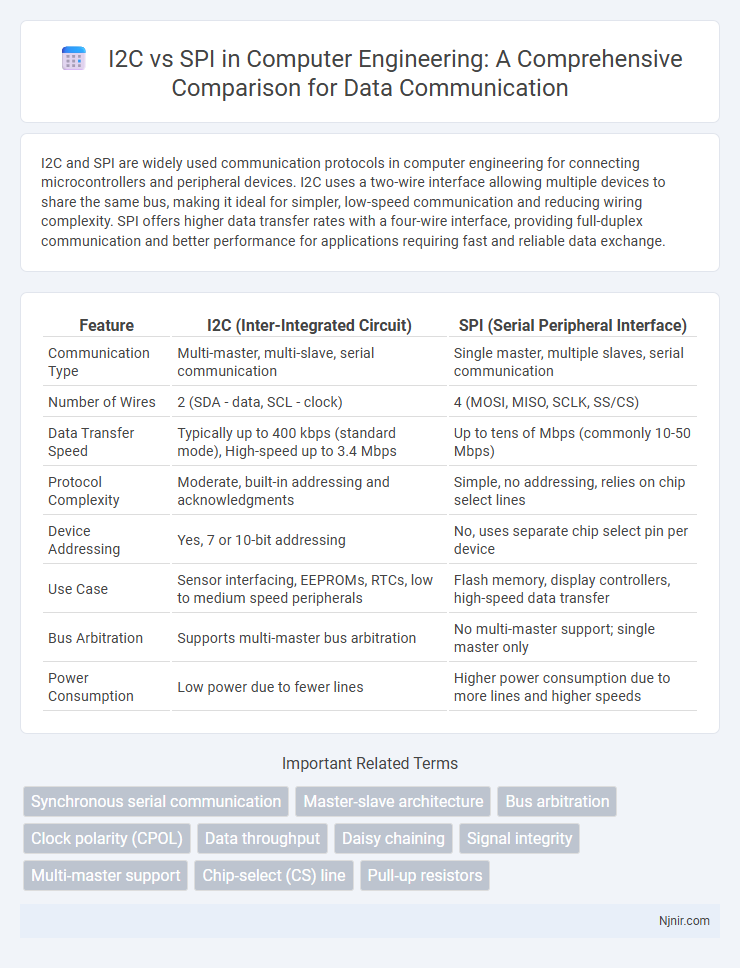
| Feature | I2C (Inter-Integrated Circuit) | SPI (Serial Peripheral Interface) |
|---|---|---|
| Communication Type | Multi-master, multi-slave, serial communication | Single master, multiple slaves, serial communication |
| Number of Wires | 2 (SDA - data, SCL - clock) | 4 (MOSI, MISO, SCLK, SS/CS) |
| Data Transfer Speed | Typically up to 400 kbps (standard mode), High-speed up to 3.4 Mbps | Up to tens of Mbps (commonly 10-50 Mbps) |
| Protocol Complexity | Moderate, built-in addressing and acknowledgments | Simple, no addressing, relies on chip select lines |
| Device Addressing | Yes, 7 or 10-bit addressing | No, uses separate chip select pin per device |
| Use Case | Sensor interfacing, EEPROMs, RTCs, low to medium speed peripherals | Flash memory, display controllers, high-speed data transfer |
| Bus Arbitration | Supports multi-master bus arbitration | No multi-master support; single master only |
| Power Consumption | Low power due to fewer lines | Higher power consumption due to more lines and higher speeds |
Overview of I2C and SPI Communication Protocols
I2C (Inter-Integrated Circuit) is a two-wire, half-duplex communication protocol primarily designed for short-distance communication between integrated circuits with multi-master and multi-slave capabilities. SPI (Serial Peripheral Interface) uses a four-wire, full-duplex protocol providing faster data transfer rates and simpler hardware connections, commonly used in applications requiring high-speed communication. Both protocols excel in embedded systems for sensor data acquisition and peripheral interfacing but differ in complexity, speed, and scalability.
Key Features and Operation Principles
I2C uses a two-wire interface consisting of a serial data line (SDA) and a serial clock line (SCL), enabling multiple devices to share the same bus with addressing for device identification. SPI employs a four-wire interface including MOSI, MISO, SCLK, and SS lines, providing full-duplex communication with faster data rates and no addressing complexity. I2C supports multi-master arbitration and clock stretching for device synchronization, while SPI operates in a master-slave configuration with higher throughput but requires separate select lines for each slave device.
Data Transfer Speeds and Bandwidth Comparison
I2C typically supports data transfer speeds up to 3.4 Mbps with limited bandwidth due to its two-wire design and shared bus architecture. SPI offers significantly higher data transfer rates, commonly reaching 10 Mbps or more, benefiting from its full-duplex, multi-wire interface that enables separate lines for data input and output. The bandwidth advantage of SPI makes it more suitable for high-speed communication requirements in embedded systems and sensors compared to I2C.
Hardware Implementation and Pin Requirements
I2C requires only two wires for communication--SDA (data) and SCL (clock)--enabling simpler hardware implementation and reduced pin usage compared to SPI's four or more lines, including MOSI, MISO, SCLK, and SS. SPI provides faster data transfer due to separate lines for data and clock signals but demands more microcontroller pins, increasing hardware complexity. Choosing between I2C and SPI depends on the balance of pin availability versus speed and complexity in device hardware design.
Communication Topology and Device Addressing
I2C communication topology uses a multi-master, multi-slave bus with two bidirectional lines (SDA for data and SCL for clock), allowing multiple devices to share the same bus and communicate via unique 7-bit or 10-bit addresses. SPI employs a master-slave topology with separate lines for clock (SCLK), data out (MOSI), data in (MISO), and individual slave select (SS) signals, requiring dedicated chip select pins for each device and no addressing scheme. I2C's built-in device addressing supports larger networks with fewer pins, while SPI offers faster, full-duplex communication but increases pin count due to dedicated slave select lines.
Power Consumption and Signal Integrity
I2C typically consumes less power than SPI due to its simpler two-wire design and lower data rates, making it suitable for battery-powered devices; however, SPI's higher-speed four-wire interface can lead to increased power draw. Signal integrity in I2C can be more susceptible to noise and signal degradation over long distances because it relies on open-drain lines with pull-up resistors, while SPI offers stronger signal integrity with separate dedicated lines for clock and data that reduce crosstalk and improve noise immunity. Power management in SPI can be optimized using shorter cables and lower clock speeds, but for ultra-low-power applications, I2C remains a preferred choice despite potential signal integrity trade-offs.
Protocol Complexity and Scalability
I2C employs a simpler two-wire protocol with addressing, enabling multiple devices on the same bus, which enhances scalability but increases protocol complexity due to arbitration and acknowledgment mechanisms. SPI uses separate lines for each device, resulting in lower protocol complexity and higher data rates but limited scalability as each additional device requires extra chip select lines. Choosing between I2C and SPI depends on the balance between protocol overhead and the need for scalable multi-device communication in embedded systems.
Use Cases and Application Scenarios
I2C is ideal for sensor networks and EEPROM communication in embedded systems due to its two-wire simplicity and multi-master capabilities, supporting moderate data rates for short-distance communication within a single device. SPI excels in applications requiring high-speed data transfer and full-duplex communication, such as SD card interfaces, display modules, and real-time data acquisition systems. Choosing between I2C and SPI depends on factors like required speed, device complexity, data throughput, and system architecture constraints.
Advantages and Disadvantages of I2C vs SPI
I2C offers simpler wiring with just two lines for data and clock, making it ideal for board-level communication and multiple devices on the same bus, but it has lower speeds and limited distance compared to SPI. SPI provides faster data transfer rates and full-duplex communication, which is beneficial for high-speed or real-time applications, but requires more pins due to separate lines for each device's chip select. I2C's built-in addressing simplifies device integration, while SPI's straightforward protocol delivers higher reliability in noisy environments but increases hardware complexity.
Choosing the Right Protocol for Your Project
Choosing the right communication protocol depends on project requirements such as speed, complexity, and pin availability. I2C offers simplicity with two wires and supports multiple devices using addressing, making it ideal for low-speed, short-distance communication in complex sensor networks. SPI provides higher speed and full-duplex communication with separate data lines, suitable for applications demanding fast data transfer and straightforward master-slave setups.
Synchronous serial communication
I2C uses a two-wire synchronous serial communication protocol with multi-master capabilities, while SPI employs a four-wire synchronous serial interface offering higher data transfer speeds and full-duplex communication.
Master-slave architecture
I2C uses a multi-master, multi-slave architecture with shared two-wire communication, while SPI employs a single-master, multi-slave setup with separate data lines for full-duplex communication.
Bus arbitration
I2C supports multi-master bus arbitration allowing multiple devices to control the bus without conflict, while SPI lacks built-in bus arbitration, requiring a single master to manage communication.
Clock polarity (CPOL)
I2C uses a fixed clock polarity with a single bi-directional clock line, while SPI allows configurable clock polarity (CPOL) to define the idle state of its separate clock line, enabling flexible timing control.
Data throughput
SPI offers higher data throughput than I2C due to its full-duplex communication and faster clock speeds, making it ideal for applications requiring rapid data transfer.
Daisy chaining
SPI supports daisy chaining multiple devices in a single bus configuration for extended communication, whereas I2C does not natively support daisy chaining and primarily operates with parallel device addressing.
Signal integrity
SPI offers superior signal integrity over I2C due to dedicated data lines and higher noise immunity, enabling faster and more reliable communication in electrically noisy environments.
Multi-master support
I2C natively supports multi-master communication allowing multiple devices to control the bus, whereas SPI typically lacks built-in multi-master capability, requiring additional hardware or protocols for multi-master setups.
Chip-select (CS) line
The SPI protocol requires a dedicated Chip-select (CS) line for each device to enable communication, whereas I2C uses unique device addresses and does not require separate CS lines.
Pull-up resistors
I2C requires external pull-up resistors on its open-drain SDA and SCL lines to ensure proper signal levels, whereas SPI uses push-pull drivers and does not need pull-up resistors.
I2C vs SPI Infographic