An H-bridge circuit provides full control over the direction of current flow to a load, enabling bidirectional motor control, while a half-bridge can only drive current in one direction at a time. The H-bridge configuration uses four switching devices arranged in a bridge, allowing efficient reversible operation and braking modes, contrasting with the simpler two-switch half-bridge that offers less flexibility. H-bridges are preferred in applications requiring precise motor control, whereas half-bridges are suitable for less complex power conversion tasks.
Table of Comparison
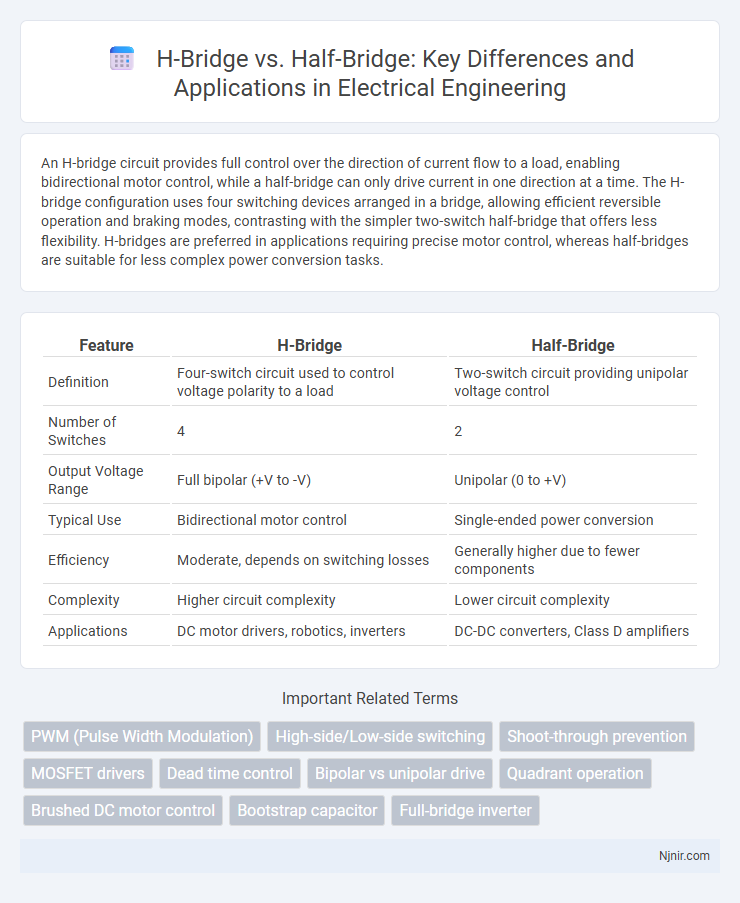
| Feature | H-Bridge | Half-Bridge |
|---|---|---|
| Definition | Four-switch circuit used to control voltage polarity to a load | Two-switch circuit providing unipolar voltage control |
| Number of Switches | 4 | 2 |
| Output Voltage Range | Full bipolar (+V to -V) | Unipolar (0 to +V) |
| Typical Use | Bidirectional motor control | Single-ended power conversion |
| Efficiency | Moderate, depends on switching losses | Generally higher due to fewer components |
| Complexity | Higher circuit complexity | Lower circuit complexity |
| Applications | DC motor drivers, robotics, inverters | DC-DC converters, Class D amplifiers |
Introduction to H-Bridge and Half-Bridge Circuits
H-bridge and half-bridge circuits are fundamental topologies used in power electronics for controlling the direction and magnitude of current through a load, such as a motor or transformer. An H-bridge consists of four switching elements arranged in an "H" configuration, enabling bidirectional current flow and full control over the load voltage polarity. In contrast, a half-bridge uses two switching elements with a midpoint capacitor, providing a simpler design for unidirectional or limited bidirectional applications with reduced component count and complexity.
Fundamental Operating Principles
An H-bridge allows control of a DC motor's direction by using four switches arranged in an "H" configuration, enabling current to flow in either direction through the load. A half-bridge consists of two switches and two capacitors, primarily used for voltage regulation and power conversion, providing only one active switching leg, which limits directional control. The fundamental difference lies in the H-bridge's capability for bidirectional current flow versus the half-bridge's unidirectional operation and simpler design for stepping voltage levels.
Key Differences: H-Bridge vs Half-Bridge
H-bridge circuits use four switches to control the direction of current through a load, enabling full bidirectional control of a DC motor, whereas half-bridge circuits consist of two switches that allow control over voltage but only enable unidirectional current flow. H-bridges provide greater flexibility for reversing motor direction and are typically used in applications requiring precise motor control, while half-bridges are simpler, more efficient for switching power in applications like DC-DC converters or motor drives with unidirectional loads. The key difference lies in the number of switches and their capability to reverse current flow, with H-bridges enabling full control and half-bridges supporting limited control with reduced component count and complexity.
Typical Applications in Electrical Engineering
H-bridge circuits are commonly used in DC motor control applications, allowing bidirectional current flow to drive motors forward or backward, making them ideal for robotics and electric vehicle systems. Half-bridge configurations are frequently applied in power electronics for inverter circuits, DC-DC converters, and amplifier designs where switching between two voltage levels is required. While H-bridge provides full control of motor direction, half-bridge excels in efficient power delivery and voltage regulation in power supply modules.
Advantages and Disadvantages of H-Bridge
The H-bridge offers precise bidirectional motor control by enabling current to flow in both directions, making it ideal for applications requiring reversible operation such as robotics and electric vehicles. Its main advantage lies in providing full control over motor speed and direction, yet it tends to have higher component complexity and increased switching losses compared to a half-bridge. Disadvantages include greater cost and potential for shoot-through current if gate driving is not properly managed, which can reduce overall efficiency and reliability.
Advantages and Disadvantages of Half-Bridge
Half-bridge circuits offer simplified design and reduced component count compared to full H-bridge configurations, leading to lower cost and smaller size in power electronics applications. Their main disadvantage is the inability to provide bidirectional current flow, limiting control in motor drive systems and restricting voltage output range. Half-bridge circuits excel in DC-DC converters and class D amplifiers but require careful management of voltage imbalance and dead-time to prevent device damage.
Power Control Capabilities Comparison
H-bridge circuits enable bidirectional current flow, allowing precise control over motor direction and speed, making them ideal for DC motor drive applications requiring full quadrature control. Half-bridge configurations provide unidirectional power delivery with simpler circuitry, suitable for applications where only voltage amplitude modulation is necessary, such as in step-up or buck converters. The H-bridge's ability to reverse polarity distinguishes it from the half-bridge, offering enhanced power control capabilities and greater flexibility in driving inductive loads.
Circuit Design Complexity
H-bridge circuits consist of four switches arranged in an H configuration, enabling bidirectional current flow for motor control, which adds design complexity due to the need for precise timing and control of all switches. Half-bridge circuits use two switches and a midpoint connection, simplifying the control scheme but limiting current direction capability, resulting in less complex layout and fewer components. The increased component count and control signals in H-bridge designs require more intricate PCB routing and gate driver circuitry compared to half-bridge designs.
Cost Analysis: H-Bridge vs Half-Bridge
H-bridge configurations typically incur higher costs than half-bridge circuits due to the increased number of power switches, usually four versus two, and the associated complexity in driving and controlling these switches. Half-bridge designs benefit from reduced component count and simpler gate driver requirements, leading to lower overall expenses, especially in applications where bidirectional current flow or full bridge operation is unnecessary. Cost analysis favors half-bridge solutions for budget-sensitive projects with moderate power needs, while H-bridge circuits justify their premium in applications demanding full motor control functionality.
Choosing the Right Bridge for Your Application
Selecting between an H-bridge and a half-bridge depends on the motor control requirements and power efficiency. An H-bridge enables bidirectional control ideal for DC motors needing forward and reverse operation, while a half-bridge suits unidirectional drives or applications requiring simpler switching topologies. Consider factors such as voltage ratings, current capacity, switching frequency, and cost to match the bridge type with your specific application demands.
PWM (Pulse Width Modulation)
H-bridge circuits enable bidirectional motor control with PWM by switching four transistors, while half-bridge circuits use two transistors for unidirectional PWM voltage regulation.
High-side/Low-side switching
H-bridge offers independent high-side and low-side switching for bidirectional motor control, while half-bridge provides single high-side and low-side switching suitable for unidirectional power stages.
Shoot-through prevention
H-bridge circuits use complementary switching with dead-time insertion to prevent shoot-through by ensuring switches on the same leg never conduct simultaneously, whereas half-bridge designs rely on similar timing control but handle only one leg, making shoot-through prevention simpler yet less versatile.
MOSFET drivers
H-bridge MOSFET drivers enable bidirectional current flow for full DC motor control, while half-bridge drivers support unidirectional current in simpler applications requiring less complex switching.
Dead time control
Dead time control in H-bridge circuits is more complex than in half-bridge designs because it requires precise timing to prevent shoot-through across four switches instead of two.
Bipolar vs unipolar drive
Bipolar drive in H-bridge circuits provides full bidirectional current control by reversing voltage polarity across the load, whereas unipolar drive in half-bridge circuits delivers current in a single direction with switching between positive voltage and ground, resulting in simpler design but less efficient torque control.
Quadrant operation
H-bridge supports all four quadrant operations enabling bidirectional current and voltage control, while half-bridge is limited to two quadrant operation with unidirectional current flow and bidirectional voltage capability.
Brushed DC motor control
H-bridge circuits provide full bidirectional control of Brushed DC motors by enabling current flow in both directions, while half-bridge configurations allow only unidirectional current flow, limiting their functionality in precise motor speed and direction control.
Bootstrap capacitor
H-bridges require larger bootstrap capacitors to maintain stable high-side gate drive voltage compared to half-bridges, ensuring efficient switching and preventing voltage drop during operation.
Full-bridge inverter
A full-bridge inverter utilizes four switches arranged in an H-bridge configuration to efficiently convert DC to AC, offering greater control and higher output voltage compared to a half-bridge inverter that uses only two switches.
H-bridge vs Half-bridge Infographic