Reactive power represents the energy stored and released by inductive or capacitive elements in an AC circuit, measured in VAR (volt-ampere reactive). Apparent power is the vector sum of real power and reactive power, measured in VA, indicating the total power supplied to the circuit. Understanding the distinction between reactive and apparent power is crucial for optimizing power factor and improving electrical system efficiency.
Table of Comparison
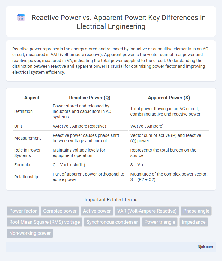
| Aspect | Reactive Power (Q) | Apparent Power (S) |
|---|---|---|
| Definition | Power stored and released by inductors and capacitors in AC systems | Total power flowing in an AC circuit, combining active and reactive power |
| Unit | VAR (Volt-Ampere Reactive) | VA (Volt-Ampere) |
| Measurement | Reactive power causes phase shift between voltage and current | Vector sum of active (P) and reactive (Q) power |
| Role in Power Systems | Maintains voltage levels for equipment operation | Represents the total burden on the source |
| Formula | Q = V x I x sin(th) | S = V x I |
| Relationship | Part of apparent power, orthogonal to active power | Magnitude of the complex power vector: S = (P2 + Q2) |
Understanding Basic Power Concepts in Electrical Engineering
Reactive power represents the energy stored and released by inductors and capacitors in an AC circuit, measured in volt-amperes reactive (VAR), and does not perform any useful work. Apparent power, measured in volt-amperes (VA), is the vector sum of active power (watts) and reactive power, indicating the total power flowing in an electrical system. Understanding the distinction between reactive and apparent power is essential for designing efficient power systems and optimizing power factor correction in electrical engineering.
Defining Reactive Power: Meaning and Significance
Reactive power represents the portion of electricity that oscillates between the source and reactive components like inductors and capacitors, measured in reactive volt-amperes (VAR). It does not perform real work but is essential for maintaining voltage levels, enabling the transfer of active power, and stabilizing electrical systems. Apparent power combines both active power (watts) and reactive power (VAR) and is measured in volt-amperes (VA), indicating the total power demand of an electrical system.
Apparent Power Explained: The Complete Power Picture
Apparent power represents the total power in an AC circuit, combining both active power (real power) and reactive power into a single measurement expressed in volt-amperes (VA). It provides a complete power picture by accounting for the power consumed by resistive loads and the energy that alternates between the source and reactive components like inductors and capacitors. Understanding apparent power is essential for sizing electrical equipment and improving power factor to enhance system efficiency.
Mathematical Relationships: Real, Reactive, and Apparent Power
Apparent power (S) in an AC circuit is the vector sum of real power (P) and reactive power (Q), expressed mathematically as S = (P2 + Q2), where S is measured in volt-amperes (VA), P in watts (W), and Q in volt-amperes reactive (VAR). Real power represents the actual work done, calculated as P = VI cos(th), while reactive power is the energy exchanged between the source and reactive components, calculated as Q = VI sin(th), with V as voltage, I as current, and th as the phase angle between them. The power factor, defined as cos(th) = P/S, quantifies the efficiency of power use, linking these quantities through trigonometric relationships essential for power system analysis.
The Role of Power Factor in AC Circuits
Reactive power represents the energy exchanged between the source and reactive components, such as inductors and capacitors, in AC circuits, while apparent power is the vector sum of real and reactive power, indicating the total power supplied by the source. The power factor, defined as the ratio of real power to apparent power, reflects the efficiency of power usage in AC systems and is crucial for minimizing energy losses and optimizing electrical equipment performance. Improving power factor reduces reactive power, lowers apparent power demand, and enhances overall system stability and cost-effectiveness.
Key Differences Between Reactive and Apparent Power
Reactive power, measured in VAR (volt-ampere reactive), represents the energy oscillating between the source and reactive components like inductors and capacitors, causing no net energy transfer but affecting voltage stability. Apparent power, measured in VA (volt-amperes), combines both active power (real power doing actual work) and reactive power, representing the total power supplied by the source. The key difference lies in their roles: reactive power affects the phase difference and magnetic fields in AC circuits, while apparent power defines the overall capacity required from the power source to deliver both useful and reactive energy components.
Effects of Reactive Power on Electrical Systems
Reactive power causes increased current flow without performing useful work, leading to higher energy losses and reduced system efficiency in electrical networks. It also induces voltage drops along transmission lines, compromising voltage regulation and potentially causing instability or equipment malfunction. Managing reactive power through compensation devices like capacitors or synchronous condensers enhances power factor and optimizes system performance.
Applications and Impacts of Apparent Power
Apparent power, measured in volt-amperes (VA), represents the total power in an AC circuit, combining both real and reactive power components essential for sizing electrical systems and selecting appropriate equipment like transformers and generators. Its impact on power distribution affects efficiency, as utilities must provide capacity for apparent power, leading to higher infrastructure costs and potential energy losses. Managing apparent power through power factor correction improves system stability and reduces demand charges on industrial and commercial customers.
Measurement and Calculation Techniques
Reactive power is measured in volt-amperes reactive (VAR) and calculated using the formula Q = V x I x sin(ph), where ph is the phase angle between voltage and current. Apparent power, measured in volt-amperes (VA), is the vector sum of active and reactive power, calculated by S = V x I or S = (P2 + Q2), with P representing active power. Measurement techniques involve using power analyzers or digital meters equipped with phase-angle detection to accurately capture voltage, current, and phase relationships, ensuring precise calculation of both reactive and apparent power components.
Managing Reactive and Apparent Power in Industrial Settings
Managing reactive power and apparent power in industrial settings is critical for optimizing energy efficiency and maintaining power quality. Reactive power, measured in VARs (volt-ampere reactive), does not perform useful work but sustains electric and magnetic fields, while apparent power, expressed in VA (volt-ampere), represents the combined effect of real and reactive power. Industrial facilities implement power factor correction techniques, such as capacitor banks and synchronous condensers, to reduce reactive power demand, improve power factor, and minimize utility penalties linked to high apparent power consumption.
Power factor
Power factor, defined as the ratio of real power to apparent power, quantifies the efficiency of electrical power usage by indicating the proportion of reactive power in the total apparent power.
Complex power
Complex power (S) represents the vector sum of active power (P) and reactive power (Q), mathematically expressed as S = P + jQ, where P is the real power consumed and Q is the reactive power exchanged between the source and load.
Active power
Active power represents the real energy consumed by a load, while reactive power oscillates between the source and load without doing useful work, together forming the apparent power as the vector sum in an AC circuit.
VAR (Volt-Ampere Reactive)
Reactive power, measured in VAR (Volt-Ampere Reactive), represents the non-working power in AC circuits responsible for energy storage in inductors and capacitors, while apparent power combines both reactive and real power, indicating the total power flow in volt-amperes (VA).
Phase angle
Reactive power (measured in VAR) is the component of apparent power (measured in VA) that causes a phase angle difference between voltage and current, representing the power oscillating between the source and reactive components.
Root Mean Square (RMS) voltage
Reactive power depends on the Root Mean Square (RMS) voltage and current phase difference, whereas apparent power is the product of the RMS voltage and RMS current regardless of phase angle.
Synchronous condenser
A synchronous condenser enhances power factor correction by supplying reactive power, thus improving the balance between reactive power (measured in VARs) and apparent power (measured in VA) in electrical power systems.
Power triangle
Reactive power represents the imaginary component, apparent power combines both real and reactive power, and the Power Triangle visually illustrates their relationship with real power as the base, reactive power as the height, and apparent power as the hypotenuse.
Impedance
Reactive power in an AC circuit is influenced by the imaginary component of impedance, while apparent power represents the combined effect of both the real (resistive) and reactive (imaginary) parts of impedance.
Non-working power
Reactive power represents non-working power in AC circuits, causing energy oscillation without performing useful work, whereas apparent power combines both reactive and active power, indicating total power flow.
Reactive power vs Apparent power Infographic