Register Transfer Level (RTL) design abstracts hardware functionality by describing data flow and control signals using hardware description languages like VHDL or Verilog, enabling easier debugging and synthesis. Gate level representation breaks down the design into individual logic gates and flip-flops, providing a detailed implementation closer to physical hardware. RTL allows designers to optimize performance and area before the synthesis process converts it into gate-level netlists for detailed validation and timing analysis.
Table of Comparison
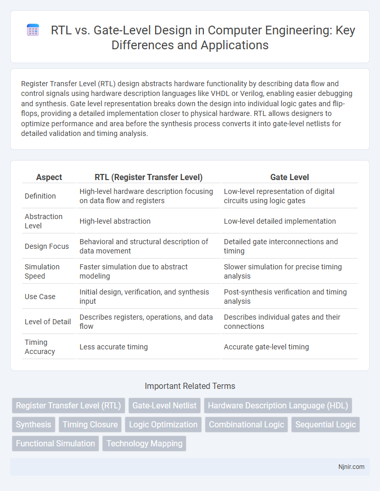
| Aspect | RTL (Register Transfer Level) | Gate Level |
|---|---|---|
| Definition | High-level hardware description focusing on data flow and registers | Low-level representation of digital circuits using logic gates |
| Abstraction Level | High-level abstraction | Low-level detailed implementation |
| Design Focus | Behavioral and structural description of data movement | Detailed gate interconnections and timing |
| Simulation Speed | Faster simulation due to abstract modeling | Slower simulation for precise timing analysis |
| Use Case | Initial design, verification, and synthesis input | Post-synthesis verification and timing analysis |
| Level of Detail | Describes registers, operations, and data flow | Describes individual gates and their connections |
| Timing Accuracy | Less accurate timing | Accurate gate-level timing |
Introduction to RTL and Gate Level Design
Register Transfer Level (RTL) design represents digital circuits using registers and the flow of data between them, allowing designers to describe hardware behavior at a higher abstraction. Gate level design details a circuit's implementation by specifying individual logic gates such as AND, OR, and NOT, providing a precise blueprint for physical hardware. RTL serves as an intermediary step that enables synthesis tools to translate behavioral descriptions into gate-level netlists, bridging high-level algorithms and physical circuit layouts.
Key Differences Between RTL and Gate Level
RTL (Register Transfer Level) describes digital circuits using high-level abstractions like registers and data flows, enabling easier design and simulation. Gate level represents circuits as interconnected logic gates, offering detailed hardware implementation and timing accuracy for synthesis and verification. RTL focuses on functional behavior and design intent, while gate level emphasizes precise hardware structure and connectivity.
Overview of RTL (Register Transfer Level)
Register Transfer Level (RTL) is a hardware description abstraction used to represent digital circuits by detailing data flow between registers and the logical operations performed on this data at each clock cycle. RTL enables designers to describe the functionality and timing of complex digital systems using languages such as VHDL or Verilog, serving as a critical step before synthesis to gate-level implementations. This abstraction facilitates efficient simulation, verification, and optimization of microprocessors, digital signal processors, and other integrated circuits.
Overview of Gate Level Modeling
Gate level modeling describes digital circuits using logic gates such as AND, OR, NOT, NAND, and NOR to represent the actual hardware implementation. It offers a detailed and precise description of circuit functionality by specifying connections and delays at the gate level, enabling accurate timing analysis and optimization. This modeling approach is crucial for verifying hardware designs before fabrication and for understanding low-level circuit behavior in FPGA and ASIC development.
Design Abstraction Levels in Digital Circuits
RTL (Register Transfer Level) abstraction focuses on describing digital circuits in terms of data flow between registers and the logical operations performed on that data, enabling efficient hardware design and verification. Gate Level abstraction represents digital circuits as interconnected logic gates and flip-flops, providing detailed implementation readiness and precise timing information essential for physical design and optimization. Understanding the distinction between RTL and Gate Level is crucial for optimizing synthesis processes, improving design accuracy, and enhancing overall performance in digital circuit development.
RTL vs Gate Level: Design Flow Comparison
RTL (Register Transfer Level) design focuses on high-level abstract representation of digital circuits using hardware description languages like VHDL or Verilog, emphasizing data flow and control signals. Gate level design translates RTL into a detailed network of logic gates and flip-flops, enabling precise timing analysis and physical implementation. The design flow moves from RTL, where functionality is verified, to gate level, which facilitates synthesis, optimization, and layout for manufacturing.
Performance and Optimization Considerations
RTL (Register Transfer Level) design focuses on high-level hardware description, enabling early performance estimation and swift architectural optimizations to improve clock speed and resource utilization. Gate-level design provides a detailed, low-level view of the circuit, allowing precise timing analysis and fine-tuning of critical paths for optimized delay and power consumption. Performance improvements depend on iterative synthesis and mapping between RTL and gate-level descriptions to balance timing, area, and power constraints effectively.
Simulation and Verification in RTL vs Gate Level
RTL simulation enables early functional verification using high-level abstractions, accelerating bug detection and design validation before synthesis. Gate-level simulation provides detailed timing accuracy and verifies the synthesized netlist against the RTL, ensuring correct logical behavior and signal integrity under real silicon conditions. Combining RTL and gate-level verification improves overall design robustness by covering both functional correctness and timing-related issues.
Use Cases and Applications
RTL (Register Transfer Level) design is primarily used for early-stage functional verification, high-level synthesis, and architectural exploration, enabling designers to model complex digital circuits efficiently. Gate-level design, on the other hand, is essential for detailed timing analysis, power estimation, and final optimization before fabrication, providing precise control over implementation specifics. Use cases for RTL include system-level simulation and prototyping, while gate-level is crucial for layout generation, detailed timing simulations, and hardware debugging.
Challenges and Best Practices
Designing at the RTL level requires addressing abstraction challenges such as managing limited visibility into gate-level timing and power constraints, which can lead to discrepancies during synthesis. Gate-level design offers precise control over timing, area, and power but faces complexity issues, longer verification cycles, and difficulties in managing large netlists. Best practices include early verification using formal methods at RTL, iterative synthesis to close timing at gate level, and employing modular design with consistent constraints to bridge the abstraction gap effectively.
Register Transfer Level (RTL)
Register Transfer Level (RTL) describes a digital circuit's data flow and timing using registers and logic gates, enabling efficient synthesis and optimization before gate-level implementation.
Gate-Level Netlist
A gate-level netlist represents a digital circuit by detailing logical gates and their interconnections, enabling precise timing analysis and synthesis optimizations beyond the behavioral abstraction of RTL descriptions.
Hardware Description Language (HDL)
RTL in Hardware Description Language (HDL) defines circuit behavior and structure at the register transfer level, enabling synthesis and simulation, while gate-level HDL describes the precise logic gates and interconnections, providing detailed implementation for physical hardware.
Synthesis
RTL synthesis transforms high-level Register Transfer Level code into optimized gate-level netlists to implement digital circuits efficiently.
Timing Closure
Gate-level design enables precise timing closure by providing accurate delay information and detailed circuit behavior, whereas RTL abstraction lacks exact timing details, making gate-level analysis essential for final timing verification.
Logic Optimization
Logic optimization at the RTL level enables more efficient circuit design by simplifying high-level behavioral descriptions before synthesis, whereas gate-level optimization fine-tunes the actual network of gates post-synthesis to reduce area, delay, and power consumption.
Combinational Logic
RTL describes combinational logic behavior using high-level constructs, while gate-level represents the exact hardware gates and interconnections implementing the same logic.
Sequential Logic
Sequential logic at the RTL level describes circuit behavior using registers and flip-flops with symbolic operations, while gate-level sequential logic specifies the exact flip-flop and gate interconnections for precise hardware implementation.
Functional Simulation
Functional simulation at the RTL level enables early verification of design logic through abstract behavioral models, while gate-level simulation provides precise timing and structural validation by simulating the synthesizable netlist.
Technology Mapping
Technology mapping transforms RTL designs into optimized gate-level netlists by selecting the best set of logic gates to meet performance, area, and power constraints.
RTL vs Gate Level Infographic