AC coupling blocks the DC component of a signal, allowing only the AC variations to pass through, which is essential for measuring small AC signals on a DC offset. DC coupling enables the entire signal, including both AC and DC components, to be transmitted without alteration, providing a true representation of the waveform. Choosing between AC and DC coupling depends on whether preserving the DC level or isolating the AC signal is critical for the measurement or application.
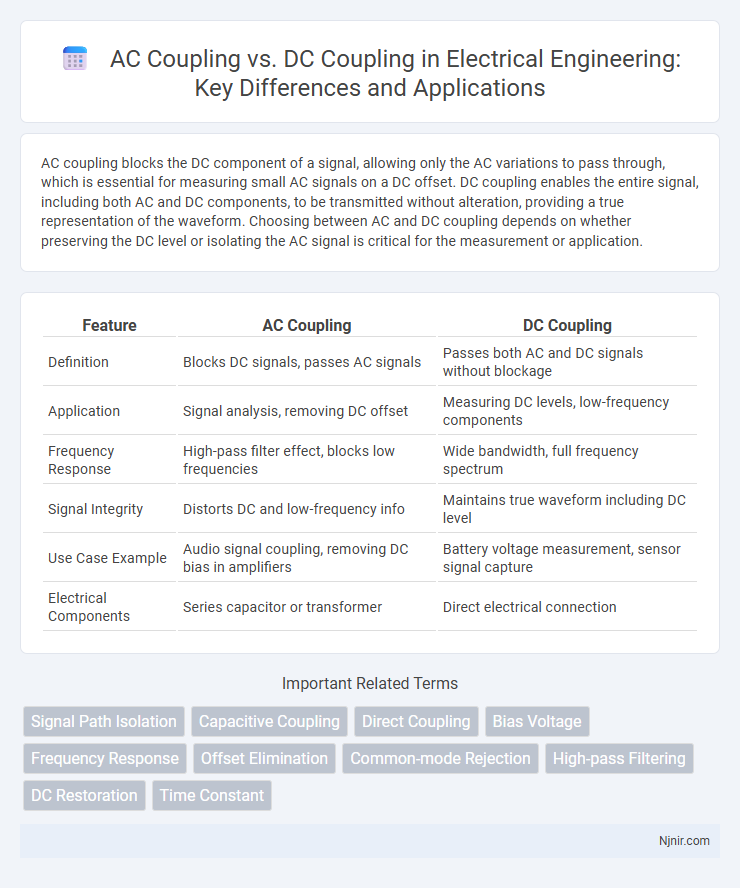
Table of Comparison
| Feature | AC Coupling | DC Coupling |
|---|---|---|
| Definition | Blocks DC signals, passes AC signals | Passes both AC and DC signals without blockage |
| Application | Signal analysis, removing DC offset | Measuring DC levels, low-frequency components |
| Frequency Response | High-pass filter effect, blocks low frequencies | Wide bandwidth, full frequency spectrum |
| Signal Integrity | Distorts DC and low-frequency info | Maintains true waveform including DC level |
| Use Case Example | Audio signal coupling, removing DC bias in amplifiers | Battery voltage measurement, sensor signal capture |
| Electrical Components | Series capacitor or transformer | Direct electrical connection |
Introduction to AC Coupling and DC Coupling
AC coupling blocks direct current (DC) components of a signal, allowing only alternating current (AC) signals to pass through, which is essential for measuring fluctuating or time-varying signals without baseline shifts. DC coupling allows both AC and DC components to pass, making it suitable for capturing the full signal waveform, including any offset or steady-state voltage. Choosing between AC and DC coupling depends on the specific application requirements, such as isolating signal variations or preserving the entire signal spectrum for accurate measurement.
Fundamental Principles of Signal Coupling
AC coupling uses a capacitor to block DC components while allowing alternating current signals to pass, isolating input stages from DC offsets. DC coupling enables the transmission of both AC and DC signals directly, preserving the entire signal waveform for accurate low-frequency or zero-frequency measurements. The choice between AC and DC coupling fundamentally depends on the need to either eliminate unwanted DC bias or maintain the true signal baseline in electronic circuits.
Key Differences Between AC and DC Coupling
AC coupling blocks the DC component of a signal, allowing only the alternating current (AC) portion to pass through, which is crucial for analyzing small AC signals superimposed on large DC offsets. DC coupling transmits both AC and DC components, preserving the original signal waveform for applications requiring accurate low-frequency or DC measurements. The choice between AC and DC coupling depends on the measurement objectives, frequency range, and signal characteristics, with AC coupling often preferred for noise reduction and DC coupling for comprehensive signal analysis.
Advantages of AC Coupling in Electrical Circuits
AC coupling in electrical circuits offers significant advantages by effectively blocking DC components, allowing the circuit to focus solely on varying AC signals and eliminating unwanted DC offset that can skew measurements. This method enhances signal integrity in amplifiers and oscilloscopes, preventing saturation and preserving the accuracy of low-frequency AC signals. AC coupling is particularly beneficial in applications involving signal transmission and processing, where isolating the AC signal from the DC bias improves overall performance and reduces noise interference.
Benefits of DC Coupling for Signal Transmission
DC coupling enables accurate transmission of low-frequency signals and true representation of the entire signal waveform without distortion or baseline shifts. It allows measurement of both AC and DC components, which is essential in applications requiring precise analysis of signal offsets or slow-varying signals. This coupling method ensures signal integrity in instrumentation, sensor interfacing, and communication systems where preserving the original signal characteristics is critical.
Common Applications of AC Coupling
AC coupling is commonly used in signal processing applications where the removal of DC offset is essential, such as in audio and communication systems to block low-frequency noise and prevent amplifier saturation. Oscilloscopes frequently employ AC coupling to focus on time-varying signals without DC interference, enhancing the clarity of waveform analysis. In measurement equipment, AC coupling ensures accurate detection of alternating signals by eliminating the influence of steady-state voltage levels.
Typical Uses of DC Coupling in Electronics
DC coupling is commonly used in electronics to measure and analyze signals containing both AC and DC components, such as in sensors, transducers, and power supply monitoring. It allows direct measurement of the true voltage levels without distortion, making it essential for accurate diagnostics in digital circuits and battery-operated devices. Applications include waveform analysis, low-frequency signal measurement, and maintaining signal integrity in amplifiers and data acquisition systems.
Practical Considerations for Coupling Selection
AC coupling filters out DC components, making it ideal for measuring small AC signals superimposed on large DC offsets, especially in audio and RF applications. DC coupling preserves both AC and DC components, essential for accurate low-frequency or DC level measurements in power electronics and sensor outputs. Selecting between AC and DC coupling depends on the signal type, measurement accuracy requirements, and the presence of DC offsets that could saturate or distort the input stage.
Troubleshooting Coupling Issues in Circuits
Troubleshooting coupling issues in circuits requires understanding the distinctions between AC and DC coupling to identify signal distortion or loss. AC coupling blocks DC components, making it effective for isolating stages and removing offsets but can cause baseline shifts or slow signal recovery in low-frequency signals. DC coupling maintains the entire signal waveform including DC levels, enabling accurate analysis but may introduce offset errors, requiring careful examination of circuit biasing and input ranges to resolve coupling-related faults.
Best Practices for Implementing AC and DC Coupling
Best practices for implementing AC coupling involve using high-quality capacitors with low equivalent series resistance (ESR) to block DC components while preserving signal integrity in AC signals. For DC coupling, ensure proper offset management and minimize input bias currents to maintain accurate signal measurement without distortion. Selecting the appropriate coupling method depends on signal frequency range, with AC coupling preferred for eliminating DC offsets and DC coupling favored for preserving low-frequency or DC information.
Signal Path Isolation
AC coupling provides signal path isolation by blocking DC components and allowing only AC signals to pass, whereas DC coupling transmits both AC and DC signals without isolation.
Capacitive Coupling
Capacitive coupling in AC coupling blocks DC signals while allowing AC signals to pass, enabling isolation of DC bias and prevention of signal distortion in electronic circuits.
Direct Coupling
Direct coupling (DC coupling) enables continuous signal transmission with zero frequency cutoff, preserving both AC and DC components for accurate low-frequency and DC measurement.
Bias Voltage
AC coupling blocks DC bias voltage allowing measurement of small AC signals without offset, while DC coupling preserves the bias voltage enabling direct observation of both AC and DC components.
Frequency Response
AC coupling blocks DC components, enhancing frequency response accuracy for signals above a specific cutoff, while DC coupling preserves all frequency components including DC, providing a full-spectrum frequency response.
Offset Elimination
AC coupling effectively eliminates offset voltage by blocking DC components, while DC coupling transmits both AC and DC signals, preserving any offset voltage.
Common-mode Rejection
AC coupling enhances common-mode rejection by blocking DC offsets and low-frequency noise, enabling more accurate signal measurement compared to DC coupling, which transmits both AC and DC components.
High-pass Filtering
AC coupling acts as a high-pass filter by blocking DC signals and allowing AC components to pass, whereas DC coupling transmits both AC and DC signals without attenuation.
DC Restoration
DC restoration techniques in AC coupling effectively eliminate the baseline drift caused by capacitive coupling, ensuring accurate measurement of low-frequency or DC signals without distorting the original waveform.
Time Constant
AC coupling filters low-frequency signals with a time constant defined by the coupling capacitor and input resistance, while DC coupling allows direct measurement of all frequencies without a time constant limitation.
AC coupling vs DC coupling Infographic