Buck converters efficiently step down voltage while maintaining high efficiency and reduced heat generation, making them ideal for applications requiring stable lower voltages from a higher input. Boost converters increase voltage levels from a lower input source, optimizing power delivery in circuits needing elevated voltage without increasing current draw significantly. Both converter types play crucial roles in power management, with buck suited for reducing voltage and boost designed for voltage amplification.
Table of Comparison
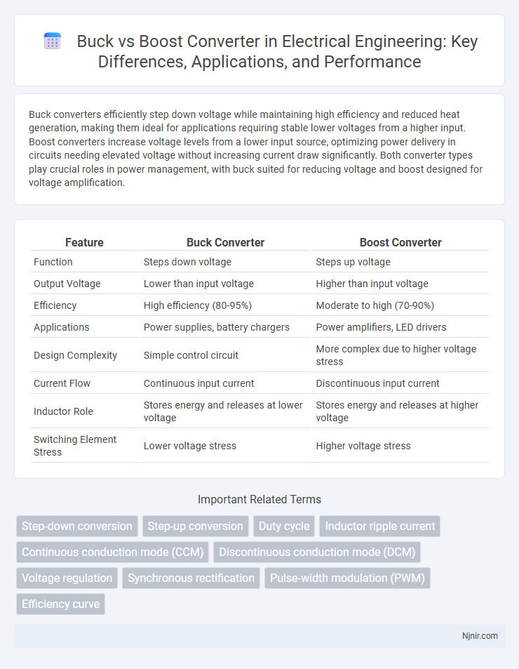
| Feature | Buck Converter | Boost Converter |
|---|---|---|
| Function | Steps down voltage | Steps up voltage |
| Output Voltage | Lower than input voltage | Higher than input voltage |
| Efficiency | High efficiency (80-95%) | Moderate to high (70-90%) |
| Applications | Power supplies, battery chargers | Power amplifiers, LED drivers |
| Design Complexity | Simple control circuit | More complex due to higher voltage stress |
| Current Flow | Continuous input current | Discontinuous input current |
| Inductor Role | Stores energy and releases at lower voltage | Stores energy and releases at higher voltage |
| Switching Element Stress | Lower voltage stress | Higher voltage stress |
Overview of Buck and Boost Converters
Buck converters step down voltage efficiently by switching and filtering, making them ideal for applications requiring lower voltage from a higher voltage source. Boost converters increase voltage from a lower input supply using an inductor-based energy storage technique, suitable for powering devices demanding higher voltage. Both converters employ pulse-width modulation (PWM) to regulate output voltage with high efficiency and minimal energy loss.
Fundamental Operating Principles
Buck converters reduce voltage by switching a transistor on and off, storing energy in an inductor, and releasing it at a lower voltage, regulated by a feedback control loop. Boost converters increase voltage by storing energy in an inductor during the transistor's on phase and releasing it to the output through a diode, resulting in a higher output voltage than the input. Both rely on pulse-width modulation (PWM) to precisely control the energy transfer and maintain steady output voltage despite varying input or load conditions.
Key Differences Between Buck and Boost Converters
Buck converters step down voltage from a higher input to a lower output, while boost converters increase voltage from a lower input to a higher output. Buck converters typically offer higher efficiency at lower output voltages and are commonly used in battery-powered devices, whereas boost converters are advantageous for applications requiring voltage elevation beyond the input supply. Key differences include their operational topology, voltage conversion ratios, and the distinct roles of inductors and switches in energy storage and transfer.
Efficiency Comparison
Buck converters typically achieve higher efficiency, often exceeding 90%, because they step down voltage with minimal energy loss. Boost converters generally have slightly lower efficiency, averaging around 80-90%, due to increased stress on components and higher voltage conversion ratios. Efficiency in both converter types depends on factors such as load conditions, switching frequency, and component quality.
Applications in Electrical Engineering
Buck converters efficiently step down voltage for applications requiring stable low-voltage DC supply such as microcontrollers and battery-powered devices. Boost converters increase voltage from low-level inputs, making them ideal for LED drivers, power amplifiers, and renewable energy systems like solar panels. Both converters are critical in power management circuits, ensuring optimized energy use and extending battery life in portable electronics.
Design Considerations
Design considerations for buck versus boost converters include input voltage range, efficiency, and component selection. Buck converters require components rated for high input current and lower output voltage, optimizing efficiency in step-down applications. Boost converters necessitate careful inductor and switch selection to handle higher output voltages and ensure stability during voltage step-up operations.
Output Voltage Regulation
Buck converters maintain output voltage regulation by stepping down input voltage with high efficiency, using pulse-width modulation to adjust the duty cycle and stabilize the output. Boost converters regulate output voltage by stepping up the input voltage, dynamically controlling inductor current and switch timing to achieve a stable, higher output voltage. Both converters rely on feedback control loops to ensure precise voltage regulation under varying load and input conditions.
Component Selection and Sizing
Component selection and sizing for buck and boost converters depend on voltage conversion requirements and efficiency targets. Buck converters use inductors with low DC resistance and capacitors with high ripple current ratings to handle step-down voltage efficiently, while boost converters require inductors with higher saturation current ratings due to increased input current stress. MOSFETs or switching transistors must be chosen based on voltage and current ratings, switching frequency, and thermal performance to ensure reliable operation and optimal power efficiency.
Common Challenges and Solutions
Buck and boost converters often face challenges such as voltage ripples, efficiency losses, and thermal management issues due to switching losses. Implementing synchronous rectification and using high-frequency inductors with low equivalent series resistance (ESR) can significantly reduce power losses and improve efficiency. Advanced control algorithms like peak current mode control enhance stability and response time, while proper heat sinking and layout optimization address thermal concerns effectively.
Future Trends in Power Conversion
Future trends in power conversion highlight the increasing integration of buck and boost converters within hybrid topologies to achieve higher efficiency and power density in renewable energy and electric vehicle applications. Advances in wide bandgap semiconductors, such as SiC and GaN devices, enable faster switching speeds and reduced losses in both buck and boost converters. Demand for smart, adaptive power management systems drives the development of digitally controlled converters that can dynamically switch between buck and boost modes for optimal voltage regulation and energy harvesting efficiency.
Step-down conversion
A buck converter efficiently performs step-down voltage conversion by reducing higher input voltage to a lower output voltage with high power efficiency using a switched inductor and diode configuration.
Step-up conversion
Boost converters efficiently perform step-up voltage conversion by increasing input voltage to a higher, stable output using inductors, switches, and diodes.
Duty cycle
The duty cycle in buck converters typically ranges from 0 to 1 to regulate output voltage below the input, whereas in boost converters, it must approach 1 to increase output voltage above the input.
Inductor ripple current
Buck converters typically exhibit lower inductor ripple current compared to boost converters due to their continuous conduction mode and lower voltage stress on the inductor.
Continuous conduction mode (CCM)
In Continuous Conduction Mode (CCM), buck converters maintain a steady inductor current to efficiently step down voltage, while boost converters sustain continuous inductor current to effectively increase voltage.
Discontinuous conduction mode (DCM)
Discontinuous conduction mode (DCM) occurs in both buck and boost converters when the inductor current falls to zero during each switching cycle, causing unique challenges in control and efficiency optimization.
Voltage regulation
Buck converters efficiently reduce voltage with high accuracy and minimal ripple, while boost converters precisely increase voltage levels maintaining stable output despite input variations.
Synchronous rectification
Synchronous rectification in buck converters significantly improves efficiency by replacing diodes with controlled MOSFETs, while in boost converters it minimizes losses during the diode conduction phase, enhancing overall power conversion efficiency.
Pulse-width modulation (PWM)
Pulse-width modulation (PWM) controls voltage conversion in buck converters by rapidly switching to reduce voltage, while in boost converters it increases voltage by adjusting duty cycle.
Efficiency curve
The efficiency curve of buck converters generally peaks at higher loads with efficiencies often exceeding 90%, while boost converters exhibit optimal efficiency at medium loads but typically suffer from greater losses at low load conditions.
buck vs boost Infographic