Buck converters efficiently step down voltage from a higher input to a lower output while maintaining high efficiency and reduced heat dissipation. Boost converters increase voltage from a lower input to a higher output, essential for applications requiring elevated voltage levels without changing current. Both converters use inductors, capacitors, and switches, but their distinct voltage transformation capabilities make them suitable for different power management scenarios in electrical engineering.
Table of Comparison
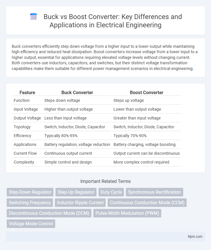
| Feature | Buck Converter | Boost Converter |
|---|---|---|
| Function | Steps down voltage | Steps up voltage |
| Input Voltage | Higher than output voltage | Lower than output voltage |
| Output Voltage | Less than input voltage | Greater than input voltage |
| Topology | Switch, Inductor, Diode, Capacitor | Switch, Inductor, Diode, Capacitor |
| Efficiency | Typically 80%-95% | Typically 70%-90% |
| Applications | Battery regulation, voltage reduction | Battery charging, voltage boosting |
| Current Flow | Continuous output current | Output current can be discontinuous |
| Complexity | Simple control and design | More complex control required |
Introduction to Buck and Boost Converters
Buck converters step down voltage efficiently by switching elements and energy storage components, making them ideal for applications requiring a lower output voltage than the input. Boost converters increase voltage levels using inductors, switches, and diodes, suitable for powering devices needing higher voltage from a lower supply. Both converter types rely on pulse-width modulation (PWM) to regulate output voltage with high efficiency across various electronic systems.
Key Principles of Operation
Buck converters step down voltage by switching the input supply on and off rapidly and using an inductor to store and release energy, ensuring a lower output voltage with high efficiency. Boost converters increase voltage by storing energy in an inductor during the switch-on phase and releasing it to the output at a higher voltage when the switch is off. Both converters regulate output voltage through pulse-width modulation, controlling the duty cycle to adjust energy transfer while minimizing power loss.
Voltage Regulation: Step-Down vs Step-Up
Buck converters regulate voltage by stepping down higher input voltages to lower, stable output levels, ideal for applications requiring efficient voltage reduction. Boost converters increase voltage from lower input levels to higher outputs, maintaining consistent voltage despite varying load conditions. Step-down converters typically achieve higher efficiency in voltage regulation for downward adjustments, while step-up converters excel in situations demanding increased voltage with controlled ripple and stability.
Circuit Configurations and Components
Buck converters use a switch, diode, inductor, and capacitor arranged to step down voltage by controlling energy transfer through the inductor during switching cycles. Boost converters configure these components differently, positioning the inductor at the input and the diode in reverse polarity to increase output voltage above the input level. Both circuits rely on pulse-width modulation (PWM) control to regulate the switching element, with specific component values designed to optimize efficiency and minimize output ripple.
Efficiency Comparison
Buck converters typically achieve efficiencies ranging from 85% to 95% by stepping down voltage with minimal power loss, making them ideal for applications requiring voltage reduction. Boost converters, designed to increase voltage, generally maintain efficiencies between 80% and 90%, with performance influenced by factors like switching frequency and component quality. Efficiency in both converter types heavily depends on the operating conditions, including load current, input voltage, and circuit design, where optimized inductor and transistor selection can significantly reduce power dissipation.
Applications in Electrical Engineering
Buck and boost converters are essential in electrical engineering for voltage regulation in power supply systems, adapting voltage levels to meet device requirements. Buck converters efficiently step down voltage in applications like battery-powered devices and LED drivers, optimizing energy usage and extending battery life. Boost converters increase voltage, crucial for applications such as electric vehicle powertrains, renewable energy systems, and portable electronics requiring stable higher voltage from lower sources.
Advantages and Limitations of Buck Converters
Buck converters offer high efficiency in voltage step-down applications, making them ideal for battery-powered devices by reducing power loss and heat generation. They deliver a stable output voltage lower than the input with minimal ripple, supporting sensitive electronics and improving overall system reliability. Limitations include complexity in design for very low output voltages and reduced efficiency when the input-to-output voltage difference is narrow, affecting performance in variable voltage environments.
Pros and Cons of Boost Converters
Boost converters efficiently increase DC voltage above the input level, making them ideal for applications requiring higher voltage from lower-voltage sources, such as battery-powered devices. Their advantages include high efficiency, minimal component count, and the ability to provide a stable output voltage despite input fluctuations. However, boost converters can generate significant electromagnetic interference (EMI), suffer from increased output voltage ripple, and have limitations in step-down voltage applications, necessitating careful design and filtering.
Selecting the Right Converter for Your Design
Choosing between a buck and boost converter depends on the input and output voltage requirements of your design. Buck converters efficiently step down voltage with high efficiency in applications where the input voltage exceeds the output voltage, while boost converters increase voltage when the input is lower than the desired output. Evaluating factors like load current, voltage range, efficiency, and size constraints ensures optimal performance and longevity in your power management system.
Summary and Future Trends in DC-DC Conversion
Buck converters efficiently step down voltage, providing high efficiency in applications like battery-powered devices, while boost converters increase voltage for devices requiring higher input levels. Emerging trends in DC-DC conversion emphasize wide-bandgap semiconductors such as GaN and SiC, enabling higher switching frequencies, reduced losses, and compact designs. Future developments focus on integrating advanced control algorithms and multi-level converter topologies to enhance power density, efficiency, and adaptability in renewable energy and electric vehicle systems.
Step-Down Regulator
A Buck converter, also known as a step-down regulator, efficiently reduces input voltage to a lower output voltage using a high-speed switching transistor, an inductor, and a diode or synchronous switch.
Step-Up Regulator
A step-up regulator, or boost converter, increases input voltage to a higher output voltage efficiently by storing energy in an inductor and releasing it through a diode and capacitor.
Duty Cycle
The duty cycle in buck converters typically ranges from 0 to 1 to reduce voltage, while in boost converters it ranges above 1 to increase voltage, directly controlling the output voltage ratio.
Synchronous Rectification
Synchronous rectification in buck and boost converters improves efficiency by replacing diodes with controlled MOSFETs, reducing conduction losses and enhancing power conversion performance.
Switching Frequency
Higher switching frequencies in buck converters generally improve transient response and reduce passive component size, whereas boost converters often balance switching frequency to optimize efficiency and minimize electromagnetic interference.
Inductor Ripple Current
Inductor ripple current in buck converters is lower compared to boost converters at equivalent power levels, resulting in reduced core losses and improved efficiency.
Continuous Conduction Mode (CCM)
Buck and Boost converters operating in Continuous Conduction Mode (CCM) maintain inductor current flowing continuously, improving efficiency and reducing current ripple compared to Discontinuous Conduction Mode (DCM).
Discontinuous Conduction Mode (DCM)
Buck and boost converters operating in Discontinuous Conduction Mode (DCM) exhibit unique inductor current waveforms and variable switching periods that impact efficiency and voltage regulation.
Pulse-Width Modulation (PWM)
Pulse-Width Modulation (PWM) in buck converters efficiently reduces voltage by switching transistors on and off at high frequencies with varying duty cycles, while in boost converters, PWM controls the duty cycle to increase output voltage above the input level.
Voltage Mode Control
Voltage Mode Control in Buck vs Boost converters optimizes output voltage regulation by adjusting duty cycle based on the error between reference and sensed output voltage, with Buck converters providing step-down voltage conversion and Boost converters enabling step-up voltage transformation.
Buck vs Boost (converter) Infographic