Unipolar signals use a single polarity voltage reference, typically ranging from zero to a positive voltage, which simplifies circuit design but may limit noise immunity. Bipolar signals alternate between positive and negative voltages relative to a zero reference, enhancing signal integrity and reducing DC bias effects in transmission lines. Choosing between unipolar and bipolar signaling depends on system requirements such as noise tolerance, power consumption, and complexity.
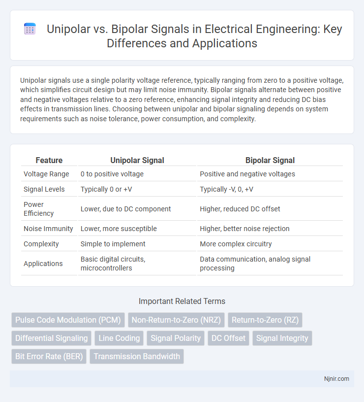
Table of Comparison
| Feature | Unipolar Signal | Bipolar Signal |
|---|---|---|
| Voltage Range | 0 to positive voltage | Positive and negative voltages |
| Signal Levels | Typically 0 or +V | Typically -V, 0, +V |
| Power Efficiency | Lower, due to DC component | Higher, reduced DC offset |
| Noise Immunity | Lower, more susceptible | Higher, better noise rejection |
| Complexity | Simple to implement | More complex circuitry |
| Applications | Basic digital circuits, microcontrollers | Data communication, analog signal processing |
Introduction to Unipolar and Bipolar Signals
Unipolar signals use a single polarity, typically positive voltage levels, to represent binary data, making them simpler and easier to generate. Bipolar signals alternate between positive and negative voltages, improving noise immunity and allowing better synchronization by balancing the signal's DC component. These fundamental differences impact signal integrity and bandwidth efficiency in digital communication systems.
Fundamental Principles of Signal Representation
Unipolar signals represent data using a single polarity, typically with voltage levels ranging from zero to a positive value, making them simpler but more susceptible to baseline wander and DC bias. Bipolar signals alternate between positive and negative voltage levels, reducing the DC component and improving noise immunity by allowing easier clock recovery and error detection. These fundamental differences affect signal integrity and performance in digital communication systems.
Characteristics of Unipolar Signals
Unipolar signals use a single polarity voltage level, typically zero and a positive voltage, to represent binary data, which simplifies circuit design but can cause a higher DC component and baseline wander. These signals have a limited voltage range, making them more susceptible to noise and less power efficient compared to bipolar signals. Unipolar signaling is commonly used in digital circuits and short-distance communications where simplicity and cost-effectiveness are prioritized over noise immunity.
Characteristics of Bipolar Signals
Bipolar signals utilize three voltage levels--positive, negative, and zero--allowing better noise immunity and reduced DC component compared to unipolar signals, which use only two voltage levels. The alternating polarity in bipolar signals helps in error detection and synchronization, improving signal integrity over long-distance communication. These characteristics result in enhanced performance in digital transmission systems where minimizing signal distortion and power consumption is critical.
Key Differences Between Unipolar and Bipolar Signals
Unipolar signals use a single polarity, typically representing digital values with voltage levels above zero, while bipolar signals alternate between positive and negative voltage levels. This key difference affects signal integrity and noise immunity; bipolar signals provide better noise rejection and reduced DC bias compared to unipolar signals. Data transmission reliability improves with bipolar signaling due to its balanced voltage swing, minimizing the risk of baseline wander and electromagnetic interference.
Advantages and Disadvantages of Unipolar Signals
Unipolar signals use a single voltage level relative to zero, which simplifies circuit design and reduces power consumption, making them ideal for low-complexity applications. However, unipolar signals are more susceptible to noise and baseline drift, leading to higher bit error rates compared to bipolar signals that use both positive and negative voltage levels. The lack of polarity variation in unipolar signaling limits AC component generation, resulting in poorer synchronization and clock recovery performance.
Advantages and Disadvantages of Bipolar Signals
Bipolar signals offer the advantage of reduced DC component, which minimizes signal distortion and improves transmission quality, especially in long-distance communication systems. These signals also enhance error detection due to their alternating polarity, making them more reliable for data integrity compared to unipolar signals. However, bipolar signals require more complex circuitry for encoding and decoding, increasing system cost and design complexity.
Applications of Unipolar and Bipolar Signals in Electrical Engineering
Unipolar signals are commonly used in digital logic circuits and simple communication systems due to their straightforward implementation and low power consumption. Bipolar signals are preferred in analog communication systems, such as AM and FM transmission, because they provide better noise immunity and signal integrity over long distances. In power electronics, bipolar signals enable efficient control of devices like H-bridge inverters, facilitating bidirectional current flow for motor drives.
Signal Noise Immunity and Error Performance
Unipolar signals, characterized by a single voltage level representing binary data, generally exhibit lower noise immunity because their reference point is zero voltage, making them more susceptible to voltage fluctuations and external interference. Bipolar signals, using alternating positive and negative voltages, inherently cancel out DC components and reduce signal distortion, enhancing noise immunity and improving error performance in communication systems. The improved signal-to-noise ratio in bipolar signaling leads to fewer bit errors, making it preferable for high-integrity data transmission over unipolar signaling.
Choosing the Right Signal Type for Your Application
Selecting between unipolar and bipolar signals depends on the specific requirements of your application, such as noise immunity, signal integrity, and power consumption. Unipolar signals, utilizing a single voltage polarity typically from 0V to a positive voltage, are simpler and consume less power but are more susceptible to noise and DC offset errors. Bipolar signals, which swing between positive and negative voltages, offer better noise rejection and improved signal fidelity, making them ideal for analog communication and environments with high electromagnetic interference.
Pulse Code Modulation (PCM)
Unipolar signals in Pulse Code Modulation (PCM) use a single voltage level for pulse representation, causing higher baseline wander and EMI compared to bipolar signals that alternate voltage polarity to improve noise immunity and signal integrity.
Non-Return-to-Zero (NRZ)
Unipolar NRZ signals use a single voltage level for binary data representation, while bipolar NRZ signals alternate between positive and negative voltage levels to represent binary ones and zeros, improving error detection and signal integrity.
Return-to-Zero (RZ)
Return-to-Zero (RZ) signaling in unipolar systems uses a single positive voltage with signal pulses returning to zero between bits, whereas bipolar RZ signaling alternates between positive and negative voltages to represent data pulses, reducing DC bias and improving error detection.
Differential Signaling
Differential signaling uses bipolar signals with two complementary voltage levels to enhance noise immunity and signal integrity compared to unipolar signaling.
Line Coding
Unipolar line coding uses a single voltage level to represent binary data, resulting in simpler circuitry but higher baseline wander, while bipolar line coding employs alternating positive and negative voltages to reduce DC bias and improve error detection.
Signal Polarity
Unipolar signals maintain a single polarity, typically positive or zero voltage, while bipolar signals alternate between positive and negative polarities to represent data.
DC Offset
Unipolar signals have a significant DC offset as they remain positive relative to zero voltage, whereas bipolar signals alternate around zero voltage, eliminating DC offset and reducing baseline drift.
Signal Integrity
Unipolar signals maintain simpler voltage levels but suffer from baseline wander and increased susceptibility to noise, while bipolar signals improve signal integrity by reducing DC bias and offering better error detection through alternating voltage levels.
Bit Error Rate (BER)
Unipolar signals exhibit higher Bit Error Rate (BER) compared to bipolar signals due to their lack of voltage polarity variation, which increases susceptibility to noise and reduces signal detection accuracy.
Transmission Bandwidth
Unipolar signals typically require less transmission bandwidth than bipolar signals due to their simpler waveform and lower frequency content.
Unipolar vs Bipolar Signal Infographic