Loop impedance measures the total resistance and reactance in an electrical circuit loop, affecting the fault current and protection device operation. Earth fault loop impedance specifically refers to the impedance through the earth path, crucial for detecting earth faults and ensuring safety by allowing sufficient fault current for protective device disconnection. Accurate measurement of both loop impedance and earth fault loop impedance is essential for validating electrical installation safety and compliance with standards.
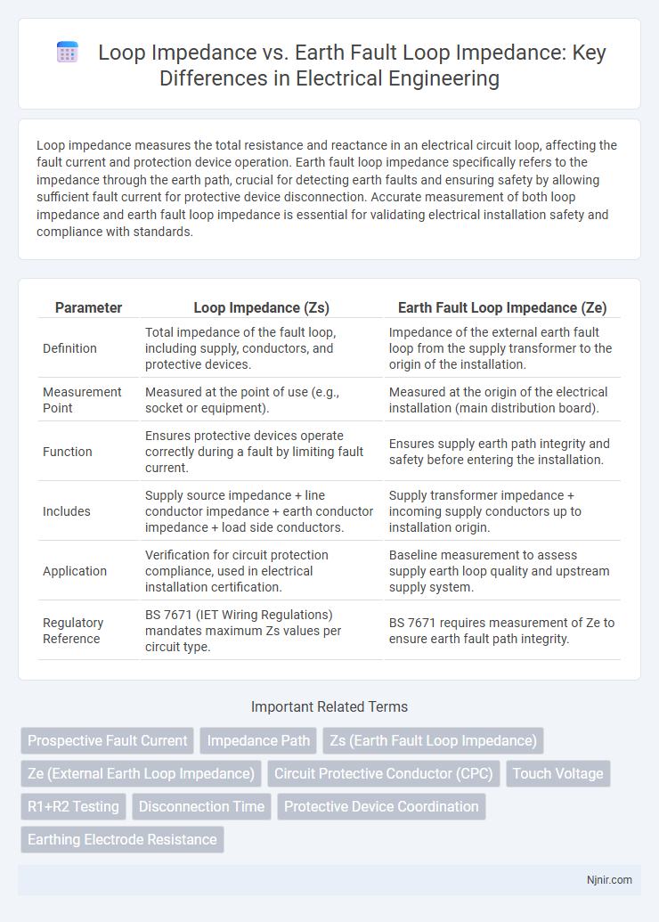
Table of Comparison
| Parameter | Loop Impedance (Zs) | Earth Fault Loop Impedance (Ze) |
|---|---|---|
| Definition | Total impedance of the fault loop, including supply, conductors, and protective devices. | Impedance of the external earth fault loop from the supply transformer to the origin of the installation. |
| Measurement Point | Measured at the point of use (e.g., socket or equipment). | Measured at the origin of the electrical installation (main distribution board). |
| Function | Ensures protective devices operate correctly during a fault by limiting fault current. | Ensures supply earth path integrity and safety before entering the installation. |
| Includes | Supply source impedance + line conductor impedance + earth conductor impedance + load side conductors. | Supply transformer impedance + incoming supply conductors up to installation origin. |
| Application | Verification for circuit protection compliance, used in electrical installation certification. | Baseline measurement to assess supply earth loop quality and upstream supply system. |
| Regulatory Reference | BS 7671 (IET Wiring Regulations) mandates maximum Zs values per circuit type. | BS 7671 requires measurement of Ze to ensure earth fault path integrity. |
Understanding Loop Impedance
Loop impedance measures the total resistance and reactance in an electrical circuit, including the supply, conductors, and protective devices, affecting fault current flow during a short circuit. Earth fault loop impedance specifically refers to the impedance of the path from the source, through the protective earth conductor, to the point of fault and back to the source, critical for ensuring protective devices trip correctly. Understanding loop impedance is essential for verifying the effectiveness of electrical safety systems and ensuring they disconnect supply quickly to prevent electric shock or fire hazards.
Defining Earth Fault Loop Impedance
Earth Fault Loop Impedance defines the total impedance in the electrical path from the point of a fault through the earth back to the source, crucial for ensuring effective fault current flow and prompt circuit protection operation. It encompasses phase conductor impedance, earth conductor impedance, and the resistance of the earth itself, influencing the trip characteristics of protective devices. Accurate measurement of Earth Fault Loop Impedance verifies the safety and reliability of electrical installations by confirming that fault currents will be sufficient to activate protective devices.
Fundamental Differences Between Loop Impedance and Earth Fault Loop Impedance
Loop impedance measures the total impedance of a circuit path including phase and neutral conductors, whereas earth fault loop impedance specifically refers to the impedance of the path from the fault point through the earth and back to the supply source. The fundamental difference lies in their application: loop impedance is used to assess the overall circuit condition, while earth fault loop impedance is critical for evaluating the effectiveness of protective devices during earth faults. Accurate measurement of earth fault loop impedance ensures proper operation of circuit breakers and prevents electric shock hazards.
Importance in Electrical Safety
Loop impedance measures the total resistance in a circuit loop, crucial for ensuring that electrical faults trigger protective devices promptly to prevent hazards. Earth fault loop impedance specifically quantifies the resistance between a live conductor and earth, directly impacting the effectiveness of fault current flow to ground, essential for rapid disconnection in fault conditions. Accurate measurement of both loop impedance and earth fault loop impedance is vital for verifying electrical installations comply with safety standards and minimize risks of electric shock and fire.
Measurement Techniques for Loop Impedance
Measurement techniques for loop impedance involve assessing the total resistance and reactance of the electrical path from the supply through the protective device to earth, ensuring proper circuit protection. Earth fault loop impedance, a specific subset, measures the impedance during an earth fault condition, focusing on the fault current path and its ability to trip protective devices promptly. Techniques use specialized instruments like loop testers or multifunction testers that apply a test current and measure voltage drop to calculate impedance accurately for both standard and earth fault loops.
Measurement Techniques for Earth Fault Loop Impedance
Earth fault loop impedance measurement focuses on assessing the total resistance and reactance within the earth fault current path, ensuring effective disconnection times for protective devices. Loop impedance involves the complete circuit path, including supply, line conductor, earth conductor, and return path, while earth fault loop impedance specifically targets the earth fault current path. Techniques such as the three-wire method, two-wire method, and clamp-on testers provide accurate earth fault loop impedance values critical for electrical safety compliance.
Impact on Circuit Protection Devices
Loop impedance measures the total resistance of the electrical path including phase and neutral conductors, while earth fault loop impedance specifically refers to the path involving the earth conductor during a fault. Accurate earth fault loop impedance values are critical for ensuring the rapid operation of circuit protection devices such as circuit breakers and RCDs, preventing electrical fires and equipment damage. High loop impedance can delay or prevent disconnection, compromising the safety and effectiveness of these protective devices.
Standards and Regulations Governing Impedance
Loop impedance measures the total resistance of an electrical circuit loop, while earth fault loop impedance specifically assesses the path resistance from a fault point back to the source via the earth conductor. Standards like the IEC 60364 and BS 7671 regulate the acceptable limits for both loop impedance and earth fault loop impedance to ensure safety and effective fault current flow for protective device operation. Compliance with these regulations is critical for minimizing electrical hazards and ensuring reliable tripping of circuit breakers during fault conditions.
Common Challenges and Troubleshooting
Loop impedance measures the total resistance in an electrical circuit path, while earth fault loop impedance specifically assesses the path through earth during a fault condition. Common challenges include inaccurate readings caused by poor connections, corrosion, or interference from nearby equipment, which can lead to false safety assessments. Troubleshooting involves verifying connections, using calibrated test equipment, and isolating circuit sections to pinpoint high-resistance faults or grounding issues.
Best Practices for Accurate Impedance Testing
Loop impedance measures the total impedance of a circuit path including the supply transformer to the point of testing, essential for verifying electrical safety. Earth fault loop impedance specifically assesses the loop formed by the earth path to ensure effective operation of protective devices during fault conditions. Best practices for accurate impedance testing include using calibrated impedance testers, confirming consistent test connections, and conducting tests at the point of intended measurement to avoid false readings and ensure reliable fault current calculations.
Prospective Fault Current
Earth Fault Loop Impedance specifically measures the total impedance in a fault current path, providing a more accurate basis for calculating the Prospective Fault Current compared to general Loop Impedance.
Impedance Path
Loop impedance measures the total resistance in the electrical circuit path including supply, conductors, and earth return, while earth fault loop impedance specifically assesses the impedance along the fault current path through the earth to ensure proper protective device operation.
Zs (Earth Fault Loop Impedance)
Zs (Earth Fault Loop Impedance) specifically measures the total impedance of the fault current path including supply, line conductor, and earth return, which is critical for ensuring effective operation of protective devices.
Ze (External Earth Loop Impedance)
External Earth Loop Impedance (Ze) represents the measured impedance from the supply transformer to the consumer's earth electrode, critically impacting the total Loop Impedance and the effectiveness of earth fault current dissipation.
Circuit Protective Conductor (CPC)
Loop impedance measures total circuit resistance including phase and neutral, while earth fault loop impedance specifically assesses resistance through the Circuit Protective Conductor (CPC) to ensure effective fault current path for safe disconnection.
Touch Voltage
Earth Fault Loop Impedance specifically measures the fault current path resistance affecting Touch Voltage levels during a ground fault, while Loop Impedance generally refers to the overall impedance in a circuit loop.
R1+R2 Testing
Loop impedance measures total circuit resistance, while earth fault loop impedance specifically assesses R1+R2 resistance during fault current testing for accurate electrical safety verification.
Disconnection Time
Earth Fault Loop Impedance specifically measures the total impedance path for fault currents and directly impacts disconnection time by ensuring protective devices trip within safety standards, whereas Loop Impedance includes both phase and earth return paths but is less focused on disconnection timing in electrical installations.
Protective Device Coordination
Earth Fault Loop Impedance specifically measures the total resistance in the fault current path impacting protective device tripping time, while Loop Impedance represents the overall circuit impedance, both critical for ensuring accurate Protective Device Coordination and minimizing fault clearance duration.
Earthing Electrode Resistance
Earth Fault Loop Impedance measures the total resistance through the earthing system including the earthing electrode resistance, whereas Loop Impedance typically refers to the impedance of the live conductor combined with the earth path resistance, with earthing electrode resistance being a critical factor in both for ensuring effective fault current dissipation.
Loop Impedance vs Earth Fault Loop Impedance Infographic