In electrical engineering, series circuits have components connected end-to-end, causing the same current to flow through each element while the total voltage divides among them. Parallel circuits feature components connected across common nodes, resulting in equal voltage across each element and a total current that sums the currents through individual branches. Understanding the distinctions between series and parallel configurations is crucial for designing efficient electrical systems and managing voltage, current, and resistance characteristics appropriately.
Table of Comparison
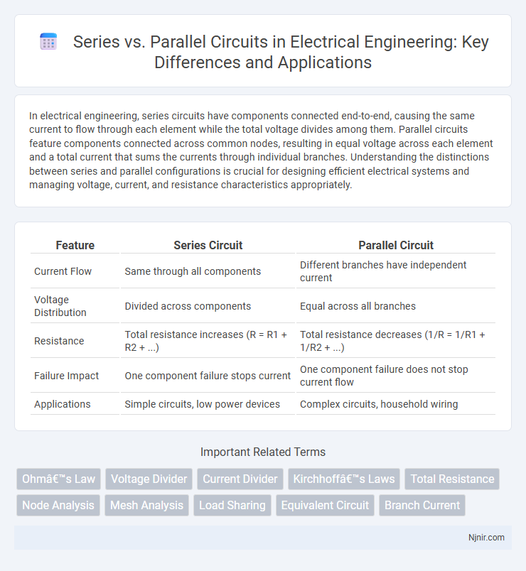
| Feature | Series Circuit | Parallel Circuit |
|---|---|---|
| Current Flow | Same through all components | Different branches have independent current |
| Voltage Distribution | Divided across components | Equal across all branches |
| Resistance | Total resistance increases (R = R1 + R2 + ...) | Total resistance decreases (1/R = 1/R1 + 1/R2 + ...) |
| Failure Impact | One component failure stops current | One component failure does not stop current flow |
| Applications | Simple circuits, low power devices | Complex circuits, household wiring |
Introduction to Series and Parallel Circuits
Series circuits feature components connected end-to-end, allowing current to flow through a single path, which makes voltage divide across each component according to its resistance. Parallel circuits connect components across common points, providing multiple paths for current flow and ensuring voltage remains consistent across each branch. Understanding these foundational configurations is essential for analyzing electrical systems and their behavior under different loads.
Basic Concepts: Voltage, Current, and Resistance
In series circuits, voltage divides across components while current remains constant through each element, resulting in total resistance equal to the sum of individual resistances. Parallel circuits exhibit constant voltage across all branches but split current according to each branch's resistance, with total resistance calculated as the reciprocal sum of the reciprocals of individual resistances. Understanding these fundamental relationships is essential for analyzing electrical behavior and designing effective circuits.
Series Circuits: Characteristics and Applications
Series circuits feature components connected end-to-end, creating a single path for current flow, which means the same current passes through each component but voltage divides across them. Common characteristics include a total resistance equal to the sum of individual resistances and voltage drops proportional to each resistor's value. Applications of series circuits are found in devices like Christmas lights and fuses, where failure in one component interrupts the entire circuit, ensuring safety and simplicity.
Parallel Circuits: Characteristics and Applications
Parallel circuits consist of multiple components connected across the same voltage source, allowing each device to operate independently without affecting others. This configuration ensures consistent voltage across all branches, making it ideal for household electrical wiring and complex electronic systems where reliability and consistent performance are crucial. Parallel circuits also enhance fault tolerance, as a failure in one branch does not disrupt the entire circuit, making them essential in applications such as lighting systems, automotive electrical systems, and power distribution networks.
Calculating Total Resistance: Series vs Parallel
Calculating total resistance in a series circuit involves summing the resistance values of all components, represented by the equation R_total = R1 + R2 + R3 + ... + Rn. In contrast, total resistance in a parallel circuit is found using the reciprocal formula 1/R_total = 1/R1 + 1/R2 + 1/R3 + ... + 1/Rn, which results in a lower overall resistance than any individual resistor. Understanding these fundamental distinctions is crucial for designing efficient electrical circuits and optimizing power distribution.
Voltage and Current Distribution in Series and Parallel Circuits
In series circuits, voltage divides across components while current remains constant throughout each element, ensuring the total voltage equals the sum of individual voltages. In parallel circuits, voltage stays uniform across all branches while current splits according to each branch's resistance, with the total current equal to the sum of currents in all branches. Understanding these distinctions is crucial for designing circuits with desired voltage and current characteristics.
Power Dissipation: Series vs Parallel Analysis
In a series circuit, power dissipation is the sum of the power across each resistor, with the same current flowing through all components, making voltage drop a key factor in total power loss. In parallel circuits, each branch receives the full voltage, causing current to divide and resulting in power dissipation calculated by the sum of voltage squared divided by each resistor's resistance. Analyzing power dissipation differences between series and parallel configurations is crucial for designing efficient electrical systems and managing thermal performance.
Practical Examples in Electrical Systems
In electrical systems, series circuits power devices like old Christmas lights where a single broken bulb stops the entire string, demonstrating the dependence on a continuous path for current flow. Parallel circuits, common in household wiring, allow multiple appliances to operate independently, ensuring that if one device fails, others continue functioning due to separate current paths. Understanding the practical distinction helps optimize safety and functionality in both small electronics and large-scale power distribution networks.
Advantages and Disadvantages of Series and Parallel Circuits
Series circuits offer advantages such as simple design and consistent current flow through all components, but they suffer from a significant disadvantage where a single fault interrupts the entire circuit. Parallel circuits provide the benefit of independent operation of components, ensuring that a failure in one branch does not affect others, and maintain consistent voltage across all branches; however, they require more complex wiring and increased material usage. Understanding these trade-offs is essential for optimizing circuit performance based on specific electrical requirements and reliability considerations.
Choosing Between Series and Parallel in Circuit Design
Choosing between series and parallel circuits depends on the desired voltage and current characteristics; series circuits provide the same current through all components with voltage divided, while parallel circuits offer the same voltage across components with current divided. Series configurations are ideal for applications requiring current continuity, such as string lights, whereas parallel circuits are preferred in household wiring to ensure consistent voltage supply and independent operation of devices. Understanding the impact on overall resistance, power distribution, and failure tolerance is crucial for optimizing circuit design efficiency and reliability.
Ohm’s Law
In electrical circuits, Ohm's Law states that the total resistance in a series configuration equals the sum of individual resistances, while in a parallel configuration, the reciprocal of the total resistance equals the sum of the reciprocals of each resistance.
Voltage Divider
In a voltage divider, resistors connected in series split the input voltage proportionally, while resistors in parallel do not create a voltage division but instead affect the total resistance and current distribution.
Current Divider
In a parallel circuit, the current divides inversely proportional to each branch's resistance, allowing the total current to split among multiple paths, unlike in a series circuit where current remains constant through all components.
Kirchhoff’s Laws
Kirchhoff's Current Law states that the total current entering a parallel circuit node equals the total current leaving, while Kirchhoff's Voltage Law indicates that the sum of voltages in a series circuit loop equals the supply voltage.
Total Resistance
Total resistance in a series circuit equals the sum of all individual resistances, while in a parallel circuit, total resistance decreases and is calculated by the reciprocal sum of each resistance's reciprocal.
Node Analysis
Node analysis simplifies circuit analysis by applying Kirchhoff's Current Law at each node to solve for node voltages in series and parallel circuits efficiently.
Mesh Analysis
Mesh analysis simplifies circuit analysis by systematically applying Kirchhoff's Voltage Law to loops in series and parallel resistor networks for calculating unknown currents.
Load Sharing
In electrical circuits, series configurations share the same current across all components while parallel configurations divide the total current, enabling effective load sharing by distributing current based on each branch's resistance.
Equivalent Circuit
Equivalent circuits simplify complex series and parallel resistor configurations by calculating total resistance as the sum in series and the reciprocal sum in parallel, enabling precise analysis of voltage, current, and power distribution.
Branch Current
In series circuits, branch current is identical across all components, while in parallel circuits, branch currents vary inversely with branch resistance.
Series vs Parallel Infographic