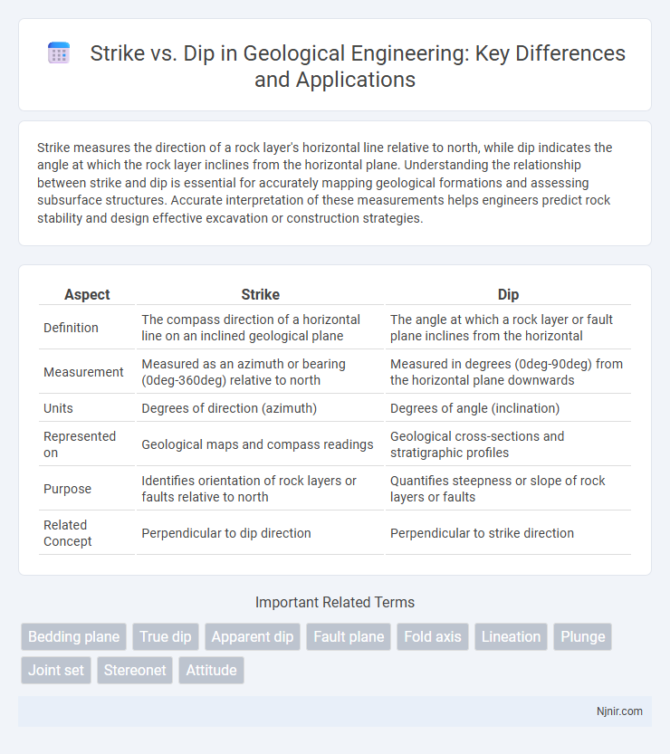
Strike measures the direction of a rock layer's horizontal line relative to north, while dip indicates the angle at which the rock layer inclines from the horizontal plane. Understanding the relationship between strike and dip is essential for accurately mapping geological formations and assessing subsurface structures. Accurate interpretation of these measurements helps engineers predict rock stability and design effective excavation or construction strategies.
Table of Comparison
| Aspect | Strike | Dip |
|---|---|---|
| Definition | The compass direction of a horizontal line on an inclined geological plane | The angle at which a rock layer or fault plane inclines from the horizontal |
| Measurement | Measured as an azimuth or bearing (0deg-360deg) relative to north | Measured in degrees (0deg-90deg) from the horizontal plane downwards |
| Units | Degrees of direction (azimuth) | Degrees of angle (inclination) |
| Represented on | Geological maps and compass readings | Geological cross-sections and stratigraphic profiles |
| Purpose | Identifies orientation of rock layers or faults relative to north | Quantifies steepness or slope of rock layers or faults |
| Related Concept | Perpendicular to dip direction | Perpendicular to strike direction |
Understanding Strike and Dip: Fundamental Concepts
Strike represents the direction of the line formed by the intersection of a rock layer or fault plane with a horizontal surface, measured relative to north. Dip indicates the angle at which the rock layer or fault plane inclines from the horizontal plane, perpendicular to the strike, providing critical information on the subsurface orientation. Mastery of strike and dip measurements aids geologists in mapping geological structures and assessing potential resource locations.
The Significance of Strike and Dip in Geological Engineering
Strike and dip are fundamental measurements in geological engineering that describe the orientation of rock layers, faults, and fractures. The strike indicates the direction of the line formed by the intersection of a rock surface with a horizontal plane, while the dip represents the angle at which the rock layer inclines relative to the horizontal plane. Accurate determination of strike and dip is crucial for slope stability analysis, underground excavation planning, and petroleum reservoir characterization, enabling engineers to assess structural integrity and potential hazards effectively.
Methods for Measuring Strike and Dip in the Field
Strike and dip are measured in the field using a clinometer and compass to determine the orientation of geological features. The strike is recorded by aligning the compass with the horizontal line on the plane of interest, while the dip is measured as the angle between the plane and the horizontal, using the clinometer. Accurate recording involves ensuring the compass is level for strike and placing the clinometer perpendicular to strike direction for the dip measurement.
Tools and Equipment for Accurate Strike and Dip Measurement
Precision in measuring strike and dip relies heavily on specialized geological tools like the Brunton compass, clinometer, and digital inclinometers. These instruments provide accurate angular readings of rock layering orientation, essential for mapping and structural analysis. Advanced tools often incorporate digital displays and data logging capabilities to enhance measurement reliability and reduce human error.
Interpretation of Strike and Dip Data in Geological Mapping
Strike represents the compass direction of the line formed by the intersection of a rock surface with a horizontal plane, while dip indicates the angle at which the rock surface inclines relative to the horizontal. Accurate interpretation of strike and dip data enables geologists to reconstruct the orientation and geometry of rock layers, faults, and folds, which is essential for creating detailed geological maps. Analyzing variations in strike and dip across an area reveals structural patterns, aiding in resource exploration and geotechnical assessments.
Common Errors in Strike and Dip Determination
Common errors in strike and dip determination often arise from incorrect identification of the bedding plane orientation, such as confusing the strike direction with the trend of linear features. Misreading the dip angle by measuring it from the horizontal instead of the perpendicular can lead to inaccurate geological mapping. Using a compass improperly or neglecting magnetic declination also causes systematic errors in recording strike measurements.
Applications of Strike and Dip in Structural Analysis
Strike and dip measurements are essential for characterizing rock orientations in structural geology, aiding in the interpretation of folds, faults, and bedding planes. Accurate strike data help geologists map the lateral direction of rock layers, while dip measurements provide insights into the angle of inclination, critical for assessing slope stability and subsurface fluid flow. These parameters are widely applied in seismic risk assessment, mining operations, and hydrocarbon reservoir modeling to predict rock behavior and guide extraction strategies.
Strike vs. Dip: Differences, Similarities, and Interrelation
Strike measures the compass direction of a horizontal line on an inclined geological plane, while dip quantifies the angle at which the plane inclines relative to the horizontal surface. Both strike and dip define the orientation of rock layers or faults, enabling geologists to understand subsurface structures and tectonic movements. Their interrelation is crucial because strike provides the direction of the line perpendicular to dip, together forming a complete spatial description of planar geological features.
Visual Representation and Notation of Strike and Dip on Maps
Strike is represented on geological maps as a short line segment indicating the direction of the horizontal intersection of a rock layer, typically measured relative to true north. Dip is illustrated by a perpendicular tick mark or arrow on the strike line, pointing down the steepest angle of inclination, with the dip angle noted numerically adjacent to the symbol. This standardized notation enables clear visualization of rock orientations, facilitating structural analysis and interpretation in field geology.
Case Studies: Real-World Impacts of Strike and Dip Analysis
Strike and dip analysis plays a crucial role in optimizing resource extraction in fields like mining and petroleum geology, as demonstrated by the precise structural mapping in the Appalachian Basin that enhanced hydrocarbon recovery rates by 15%. In the seismic evaluation of the San Andreas Fault, accurate strike and dip measurements improved earthquake risk predictions, directly influencing urban planning and infrastructure resilience. Case studies from the Norwegian Continental Shelf show that integrating strike and dip data with 3D seismic models led to more accurate reservoir characterizations, reducing drilling risks and financial losses.
Bedding plane
The bedding plane's strike represents the horizontal direction of the plane, while the dip indicates the angle at which the plane inclines downward from the strike.
True dip
True dip is the maximum angle of inclination of a rock layer measured perpendicular to its strike direction.
Apparent dip
Apparent dip measures the inclination of a geological layer observed in a direction not perpendicular to the strike, resulting in a dip angle smaller than the true dip.
Fault plane
Strike measures the horizontal direction of the fault plane relative to north, while dip indicates the angle at which the fault plane inclines downward from the horizontal.
Fold axis
The fold axis is a linear feature representing the hinge line of a fold, characterized by its plunge and trend, which differs from strike and dip that describe planar rock orientations.
Lineation
Lineation refers to the linear structural features in rocks, measuring their orientation independently from the strike and dip of planar surfaces.
Plunge
Plunge is the angle at which a geological feature, such as a fold axis or lineation, inclines downward from the horizontal plane, differing from strike, which is the compass direction of a horizontal line on the feature.
Joint set
Joint sets are typically characterized by their consistent strike directions and variable dip angles, reflecting the structural geology of rock formations.
Stereonet
Strike represents the compass direction of a rock layer's horizontal line, while dip indicates the angle of inclination perpendicular to strike, and Stereonet software precisely plots these orientations for geological analysis.
Attitude
Strike represents the horizontal direction of a rock layer, while dip indicates the angle of inclination relative to the horizontal plane.
strike vs dip Infographic