Boost converters increase voltage from a lower input level to a higher output level, making them ideal for applications requiring voltage step-up, whereas buck converters decrease voltage from a higher input to a lower output, optimizing power efficiency in devices needing voltage step-down. Both converters utilize pulse-width modulation (PWM) for voltage regulation but differ in their inductor and switch configurations, impacting their efficiency and ripple characteristics. Selecting between boost and buck converters depends on the specific voltage requirements and power conditions of the electrical system.
Table of Comparison
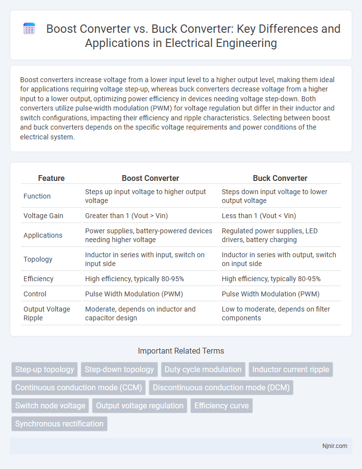
| Feature | Boost Converter | Buck Converter |
|---|---|---|
| Function | Steps up input voltage to higher output voltage | Steps down input voltage to lower output voltage |
| Voltage Gain | Greater than 1 (Vout > Vin) | Less than 1 (Vout < Vin) |
| Applications | Power supplies, battery-powered devices needing higher voltage | Regulated power supplies, LED drivers, battery charging |
| Topology | Inductor in series with input, switch on input side | Inductor in series with output, switch on input side |
| Efficiency | High efficiency, typically 80-95% | High efficiency, typically 80-95% |
| Control | Pulse Width Modulation (PWM) | Pulse Width Modulation (PWM) |
| Output Voltage Ripple | Moderate, depends on inductor and capacitor design | Low to moderate, depends on filter components |
Introduction to Power Converters
Power converters regulate electrical energy flow by transforming voltage levels to meet system requirements. A buck converter specifically steps down voltage efficiently using a switching element, inductor, and capacitor to provide stable output. Boost converters increase voltage from a lower input, making them essential for applications requiring voltage elevation while maintaining energy efficiency.
Overview of Boost Converters
Boost converters are DC-DC power converters designed to increase input voltage to a higher output voltage, commonly used in battery-powered devices and renewable energy systems. They operate by storing energy in an inductor during the switch-on phase and releasing it to the output through a diode during the switch-off phase, resulting in a voltage step-up. Key advantages of boost converters include high efficiency, simplicity in design, and the ability to provide a regulated output voltage above the input voltage.
Overview of Buck Converters
Buck converters are DC-DC power converters designed to step down voltage efficiently by switching elements and energy storage components such as inductors and capacitors. They operate by rapidly switching the input voltage on and off, storing energy in the inductor during the on phase and releasing it during the off phase to produce a lower, regulated output voltage. Widely used in battery-powered devices, power supplies, and voltage regulation applications, buck converters offer high efficiency and precise voltage control compared to linear regulators.
Operating Principles: Boost vs Buck
A Boost converter increases output voltage above the input voltage by storing energy in an inductor and releasing it through a diode and capacitor during the switch-off phase. A Buck converter reduces output voltage below the input voltage using a switching transistor that connects and disconnects the input to an inductor and capacitor network. Both converters rely on pulse-width modulation to regulate the duty cycle, controlling the energy transferred and maintaining the desired output voltage.
Key Differences in Circuit Topology
Boost converters increase output voltage above the input by using an inductor, a diode, a switch, and a capacitor arranged to store energy and release it at a higher voltage. Buck converters reduce output voltage below the input by controlling the switch and diode in a topology that steps down voltage while maintaining current flow. The main circuit topology difference lies in the switch position and energy transfer method, with boost converters charging the inductor directly from the input and buck converters connecting the inductor between the switch and output.
Voltage Conversion and Output Characteristics
A Boost converter increases output voltage above the input voltage by storing energy in an inductor and releasing it at a higher voltage, suitable for applications requiring voltage step-up. A Buck converter reduces output voltage below the input voltage by switching a transistor and diode to regulate energy transfer, ideal for voltage step-down scenarios. Output characteristics differ as Boost converters typically have discontinuous current flow and higher voltage ripple, while Buck converters provide continuous current flow with lower voltage ripple and more stable output voltage.
Efficiency Considerations
Boost converters typically exhibit lower efficiency at light loads due to increased switching losses and conduction losses from higher current ripple compared to buck converters, which maintain higher efficiency across a broader load range. Buck converters benefit from simpler topology and lower voltage stress on components, resulting in reduced power dissipation and improved efficiency, especially in step-down voltage applications. Efficiency optimization in boost converters requires careful design of inductor selection, switching frequency, and synchronous rectification to minimize losses inherent in voltage step-up processes.
Applications of Boost and Buck Converters
Boost converters are widely used in applications requiring voltage step-up, such as battery-powered devices, renewable energy systems like solar panels, and electric vehicles where higher voltage levels enable efficient power delivery. Buck converters find extensive application in voltage regulation for processors, LED drivers, and power supply units, providing stable, lower voltage outputs essential for sensitive electronic components. Both converters optimize energy efficiency and are critical in designing compact, reliable power management solutions across consumer electronics and industrial systems.
Design Challenges and Solutions
Design challenges in boost converters include managing high voltage stresses and controlling output voltage ripple, which require robust switch components and advanced feedback control algorithms. Buck converters face difficulties in minimizing conduction losses and electromagnetic interference, addressed through synchronous rectification and optimized PCB layout techniques. Both converters benefit from adaptive switching frequency and soft-switching methods to improve efficiency and reduce thermal dissipation.
Choosing the Right Converter for Your Project
Selecting the right converter depends on your project's voltage requirements and efficiency goals. Boost converters increase voltage from a lower input source, ideal for applications needing higher output voltage than the supply. Buck converters step down voltage efficiently, making them suitable for powering lower voltage devices from higher voltage sources.
Step-up topology
A Boost converter is a step-up DC-DC converter that increases input voltage to a higher output voltage, unlike a Buck converter which performs step-down voltage conversion.
Step-down topology
A Boost converter increases voltage in step-up topology, whereas a Buck converter efficiently reduces voltage in step-down topology for power regulation.
Duty cycle modulation
Duty cycle modulation in boost converters increases output voltage by extending the switch on-time above 50%, whereas buck converters reduce output voltage by decreasing the switch on-time below 50%.
Inductor current ripple
Boost converters generally exhibit higher inductor current ripple compared to buck converters due to their operation in step-up voltage mode, impacting efficiency and electromagnetic interference.
Continuous conduction mode (CCM)
In Continuous Conduction Mode (CCM), a Boost converter efficiently steps up input voltage by maintaining inductor current flow without interruption, whereas a Buck converter regulates output voltage by smoothly reducing input voltage while sustaining continuous inductor current.
Discontinuous conduction mode (DCM)
Boost converters operating in Discontinuous Conduction Mode (DCM) exhibit higher voltage stress and reduced efficiency compared to Buck converters, which maintain lower voltage stress and improved control during DCM operation.
Switch node voltage
The switch node voltage in a Boost converter rises above the input voltage during switching, while in a Buck converter it remains below the input voltage, directly affecting efficiency and component stress.
Output voltage regulation
Boost converters increase output voltage above input voltage while maintaining stable regulation, whereas buck converters reduce output voltage below input voltage with precise voltage control.
Efficiency curve
Boost converters generally exhibit lower efficiency at low output voltages due to increased conduction losses, while buck converters maintain higher efficiency across a wide range of load conditions, especially at high output voltages.
Synchronous rectification
Synchronous rectification in boost converters enhances efficiency by replacing diodes with controlled MOSFETs to minimize conduction losses, unlike traditional buck converters where synchronous rectification is standard for reducing voltage drop during step-down conversion.
Boost converter vs Buck converter Infographic