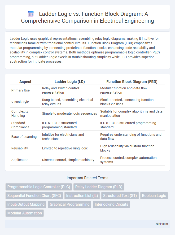
Ladder Logic uses graphical representations resembling relay logic diagrams, making it intuitive for technicians familiar with traditional control circuits. Function Block Diagram (FBD) emphasizes modular programming by connecting predefined function blocks, enhancing code reusability and scalability in complex control systems. Both methods optimize programmable logic controller (PLC) programming, but Ladder Logic excels in troubleshooting simplicity while FBD provides superior abstraction for intricate processes.
Table of Comparison
| Aspect | Ladder Logic (LD) | Function Block Diagram (FBD) |
|---|---|---|
| Primary Use | Relay and switch control representation | Modular function and data flow representation |
| Visual Style | Rung-based, resembling electrical relay circuits | Block-oriented, connecting function blocks via lines |
| Complexity Handling | Simple to moderate logic sequences | Suitable for complex algorithms and data manipulation |
| Standard Compliance | IEC 61131-3 structured programming standard | IEC 61131-3 structured programming standard |
| Ease of Learning | Intuitive for electricians and technicians | Requires understanding of functions and data flow |
| Reusability | Limited to repetitive rung logic | High reusability via custom function blocks |
| Application | Discrete control, simple machinery | Process control, complex automation systems |
Introduction to Ladder Logic and Function Block Diagram
Ladder Logic (LD) is a graphical programming language resembling electrical relay logic, widely used for designing and documenting industrial control systems in programmable logic controllers (PLCs). Function Block Diagram (FBD) organizes complex control processes through interconnected function blocks, each performing specific operations, enabling modular and reusable designs. Both LD and FBD serve as standardized IEC 61131-3 PLC programming languages, enhancing clarity and efficiency in automation projects.
Historical Evolution of PLC Programming Languages
Ladder Logic originated in the 1960s as a graphical programming language mimicking electrical relay logic, designed to ease the transition for electricians into programmable logic controllers (PLCs). Function Block Diagram (FBD) emerged in the 1970s, offering modular, reusable blocks to represent functions, improving complex control system design and promoting structured programming. The evolution of PLC programming languages reflects the shift from relay-based schematics towards modular, scalable software engineering principles in industrial automation.
Core Principles of Ladder Logic
Ladder Logic is a graphical programming language that mimics electrical relay logic, using symbols like contacts and coils to represent control processes, prioritizing simplicity and real-time operation. Its core principles involve the use of rungs to create logical expressions resembling electrical circuits, enabling straightforward troubleshooting and intuitive understanding for engineers familiar with relay control systems. Ladder Logic excels in sequential control and discrete input/output handling, making it ideal for industrial automation tasks requiring reliability and ease of visualization.
Fundamentals of Function Block Diagram
Function Block Diagram (FBD) represents control functions through interconnected blocks that perform specific operations, making it ideal for visualizing complex processes in automation systems. Each function block contains inputs, outputs, and configurable parameters, facilitating modular programming and reuse in programmable logic controllers (PLCs). FBD excels in handling analog signals and continuous data flows, providing clear, intuitive system design compared to the relay-oriented, discrete step-by-step approach of Ladder Logic.
Syntax and Visual Differences
Ladder Logic uses graphical symbols resembling electrical relay circuits, with rungs representing control instructions that flow left to right, making it intuitive for electricians. Function Block Diagram (FBD) employs interconnected blocks representing functions or operations, with inputs and outputs linked by lines, emphasizing modular design and data flow. Syntax-wise, Ladder Logic consists of contacts and coils arranged in a linear sequence, while FBD is organized as networks of reusable function blocks, enhancing readability for complex control processes.
Application Areas in Industrial Automation
Ladder Logic is primarily used for simple, discrete control applications in industrial automation, including motor starters, conveyor systems, and safety interlocks due to its ease of understanding and troubleshooting for electricians and technicians. Function Block Diagram excels in complex process control, continuous systems, and batch processing environments by allowing modular programming and reuse of functional blocks, making it ideal for industries like chemical processing, pharmaceuticals, and food and beverage manufacturing. Both programming languages are integral to PLC programming but are selected based on specific application requirements and complexity in automated systems.
Advantages and Disadvantages of Ladder Logic
Ladder Logic offers intuitive visualization resembling electrical relay diagrams, making it easier for electricians and technicians to troubleshoot and maintain industrial control systems. Its simplicity supports rapid programming for basic sequential control but becomes cumbersome and less efficient for complex processes requiring intricate data handling or advanced functions. Limited scalability and difficulty in representing analog signals pose challenges compared to the more flexible and modular Function Block Diagram approach.
Pros and Cons of Function Block Diagram
Function Block Diagram (FBD) offers a visual programming approach that simplifies complex control systems by using interconnected blocks representing functions, making it easier to understand and modify. Its main advantage lies in modular design and reusability, which enhances maintainability and scalability in automation projects. However, FBD can be less intuitive for sequential control compared to Ladder Logic, and debugging may be more challenging due to the abstraction of logic within function blocks.
Real-World Case Studies and Examples
Ladder Logic excels in discrete control applications such as manufacturing assembly lines and motor start-stop sequences, offering intuitive graphical representation for electricians and engineers. Function Block Diagram is preferred in process control systems like chemical plants and wastewater treatment, enabling modular programming of complex algorithms and analog signal manipulation. Real-world case studies demonstrate Ladder Logic's effectiveness in event-driven control, while Function Block Diagrams optimize continuous process automation and system scalability.
Choosing the Right Language for Your Project
Selecting between Ladder Logic and Function Block Diagram depends on project complexity and user familiarity; Ladder Logic excels in simple relay-based control and troubleshooting, while Function Block Diagram suits complex data processing and modular designs. Ladder Logic's intuitive graphical representation mirrors electrical circuits, making it ideal for electricians, whereas Function Block Diagram offers reusable blocks for easier scaling and maintenance. Consider project requirements, team expertise, and future expansion when deciding the best programming language for efficient automation implementation.
Programmable Logic Controller (PLC)
Ladder Logic offers intuitive relay-based programming for PLCs with straightforward troubleshooting, while Function Block Diagram provides modular, graphical function blocks ideal for complex process control and data handling in Programmable Logic Controller applications.
Relay Ladder Diagram (RLD)
Relay Ladder Diagram (RLD) uses symbolic relay logic to simplify programming and troubleshooting in industrial automation compared to the graphical function blocks of Function Block Diagram (FBD).
Sequential Function Chart (SFC)
Sequential Function Chart (SFC) enhances Ladder Logic and Function Block Diagram (FBD) by providing a clear, stepwise visualization of complex industrial control sequences, improving programming efficiency and system reliability.
Instruction List (IL)
Instruction List (IL) offers a low-level, text-based programming approach optimized for precise control and compact coding, contrasting with Ladder Logic's graphical representation and Function Block Diagram's modular block-based design in PLC programming.
Structured Text (ST)
Structured Text (ST) offers superior flexibility and scalability over Ladder Logic and Function Block Diagram (FBD) by enabling complex algorithms and advanced data handling in industrial automation programming.
Boolean Logic
Ladder Logic uses graphical symbols resembling electrical relay logic with explicit Boolean operators for control of digital inputs and outputs, whereas Function Block Diagram employs interconnected function blocks that internally process Boolean logic for modular and reusable control system design.
Input/Output Mapping
Ladder Logic uses contact and coil symbols for intuitive input/output mapping representing physical switches and relays, while Function Block Diagram employs graphical blocks with clearly defined input/output terminals for modular and reusable control logic configurations.
Graphical Programming
Ladder Logic and Function Block Diagram are graphical programming languages used in industrial automation, where Ladder Logic mimics electrical relay schematics for intuitive troubleshooting, while Function Block Diagram offers modular and reusable blocks for complex control systems.
Interlocking Circuits
Ladder Logic uses relay-like contacts to create interlocking circuits with intuitive on/off control, while Function Block Diagram employs modular blocks for complex interlocking logic with enhanced scalability and reusability.
Modular Automation
Function Block Diagram offers enhanced modular automation by enabling reusable, interconnected function blocks, whereas Ladder Logic provides simpler, linear control sequences primarily suited for straightforward automation tasks.
Ladder Logic vs Function Block Diagram Infographic