RC filters are commonly used for their simplicity and cost-effectiveness in low-frequency applications, providing moderate filtering by combining resistors and capacitors to attenuate unwanted signals. LC filters, incorporating inductors and capacitors, offer superior performance at higher frequencies with sharp cutoff characteristics and lower power dissipation. The choice between RC and LC filters depends on the frequency range, efficiency requirements, and complexity tolerance in the electrical engineering design.
Table of Comparison
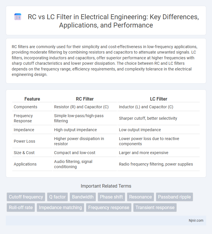
| Feature | RC Filter | LC Filter |
|---|---|---|
| Components | Resistor (R) and Capacitor (C) | Inductor (L) and Capacitor (C) |
| Frequency Response | Simple low-pass/high-pass filtering | Sharper cutoff, better selectivity |
| Impedance | High output impedance | Low output impedance |
| Power Loss | Higher power dissipation in resistor | Lower power loss due to reactive components |
| Size & Cost | Compact and low-cost | Larger and more expensive |
| Applications | Audio filtering, signal conditioning | Radio frequency filtering, power supplies |
Introduction to RC and LC Filters
RC filters consist of resistors and capacitors arranged to selectively pass or block specific frequency ranges, widely used in audio and signal processing applications. LC filters use inductors and capacitors to achieve sharper frequency selectivity with lower losses, commonly found in radio frequency circuits and communication systems. The choice between RC and LC filters depends on desired frequency response, component size, and application requirements.
Basic Principles of RC and LC Filters
RC filters utilize a resistor and capacitor to regulate signal frequency by creating phase shifts and amplitude attenuation, primarily affecting high or low frequencies depending on configuration. LC filters combine inductors and capacitors to form resonant circuits that offer sharper cutoff frequencies and better selectivity with minimal power loss. The fundamental principle of RC filters relies on the frequency-dependent impedance of capacitors, while LC filters exploit resonance between inductive and capacitive reactances for more precise frequency filtering.
Circuit Configurations of RC and LC Filters
RC filters typically consist of a resistor and capacitor arranged in either series or parallel configurations, forming low-pass or high-pass filters with simple and cost-effective designs. LC filters employ inductors and capacitors in various series-parallel combinations, enabling more selective frequency filtering with sharper roll-off characteristics and higher quality factors. The circuit configuration of LC filters allows for band-pass and band-stop responses, making them suitable for applications requiring precise frequency tuning and minimal signal loss.
Frequency Response Comparison
RC filters exhibit a gradual roll-off rate of approximately 20 dB per decade, making them suitable for basic frequency attenuation with moderate selectivity. LC filters provide a much sharper cutoff and higher Q-factor due to the resonance between inductors and capacitors, resulting in superior frequency selectivity and lower insertion loss. The frequency response of LC filters is highly tunable, allowing precise control over bandwidth and attenuation, whereas RC filters are simpler but less effective in applications requiring steep filter characteristics.
Attenuation and Selectivity Characteristics
RC filters exhibit moderate attenuation and lower selectivity due to the resistive component limiting the steepness of their frequency response. LC filters provide higher attenuation and superior selectivity, leveraging inductors and capacitors to create sharper cutoff slopes and better frequency discrimination. The inherent quality factor (Q factor) of LC circuits significantly enhances their ability to suppress unwanted frequencies compared to RC filters.
Impedance Considerations
RC and LC filters exhibit distinct impedance characteristics that influence their frequency response and signal integrity. In RC filters, the resistor provides a fixed impedance while the capacitor's reactance decreases with frequency, resulting in a frequency-dependent impedance that affects the filter's cutoff behavior. LC filters leverage the inductive reactance of the inductor, which increases with frequency, in combination with the capacitor's decreasing reactance, creating sharper impedance variations for more selective filtering and better attenuation of unwanted frequencies.
Efficiency and Power Losses
RC filters generally exhibit higher power losses due to the resistive element dissipating energy as heat, which decreases overall efficiency, especially at higher frequencies. LC filters utilize inductors and capacitors that ideally store and release energy without resistive dissipation, resulting in lower power losses and superior efficiency for signal filtering. The choice between RC and LC filters depends on the specific application requirements, where LC filters are preferred for minimizing power loss and maximizing efficiency in high-frequency circuits.
Component Size and Cost Analysis
RC filters typically feature smaller resistor and capacitor components, making them more compact and cost-effective for low-frequency applications. LC filters require inductors, which tend to be larger, heavier, and more expensive due to the coil windings and core materials, especially at low frequencies. For high-frequency or precision filtering, the increased size and cost of LC components often justify their superior performance and lower power loss compared to RC filters.
Typical Applications in Electrical Engineering
RC filters are commonly used in audio signal processing and sensor circuits for smoothing and noise reduction due to their simplicity and low cost. LC filters find typical applications in radio frequency (RF) systems, such as tuners and transmitters, because of their high selectivity and ability to handle high frequencies with minimal power loss. Both filter types are essential in power supply design for ripple attenuation and signal conditioning in analog circuits.
Selection Criteria: When to Use RC or LC Filters
RC filters are preferred in low-frequency applications due to their simplicity, lower cost, and ease of integration in compact circuits, making them ideal for audio and signal conditioning tasks. LC filters excel in high-frequency scenarios, such as RF and communication systems, offering superior selectivity, higher quality factors (Q), and lower insertion loss for precise frequency separation. Selection criteria prioritize frequency range, application complexity, and performance requirements, with RC filters favored for frequencies below a few hundred kilohertz and LC filters dominating in megahertz and gigahertz domains.
Cutoff frequency
The cutoff frequency of an RC filter is determined by the resistor and capacitor values using the formula \( f_c = \frac{1}{2\pi RC} \), while for an LC filter, it depends on the inductance and capacitance values calculated by \( f_c = \frac{1}{2\pi\sqrt{LC}} \).
Q factor
The Q factor of an LC filter is typically higher than that of an RC filter, resulting in sharper frequency selectivity and reduced energy loss.
Bandwidth
An RC filter typically offers a wider bandwidth due to its single reactive component, while an LC filter provides a narrower bandwidth and sharper frequency selectivity because of its resonant inductance-capacitance combination.
Phase shift
An RC filter exhibits a phase shift ranging from 0deg to -90deg, while an LC filter can achieve phase shifts approaching +-180deg, enabling superior frequency response and signal separation.
Resonance
LC filters exhibit sharp resonance peaks due to their inductive and capacitive energy exchange, enabling selective frequency attenuation, whereas RC filters lack true resonance, resulting in more gradual frequency roll-off.
Passband ripple
An LC filter typically exhibits lower passband ripple compared to an RC filter due to its higher Q-factor and energy storage capabilities in inductors and capacitors.
Roll-off rate
An LC filter typically achieves a steeper roll-off rate of 40 dB/decade per reactive element compared to the 20 dB/decade roll-off rate of an RC filter.
Impedance matching
An RC filter typically offers higher impedance at high frequencies, improving impedance matching in signal processing, while an LC filter provides better impedance matching across a wider frequency range due to its resonant characteristics.
Frequency response
RC filters exhibit a frequency response characterized by a gradual roll-off determined by the resistor and capacitor values, whereas LC filters provide a sharper frequency cutoff with higher selectivity due to their inductive and capacitive resonance.
Transient response
RC filters exhibit slower transient response with gradual voltage changes due to resistor-capacitor time constants, whereas LC filters deliver faster transient response and sharper signal transitions by leveraging inductor-capacitor resonance.
RC vs LC filter Infographic