Oscilloscopes capture and display analog signals with high temporal resolution, making them ideal for analyzing signal waveforms and voltage changes over time. Logic analyzers specialize in monitoring and recording digital signals, providing detailed timing and logic state information across multiple channels simultaneously. Choosing between an oscilloscope and a logic analyzer depends on whether the task involves analog signal inspection or complex digital system debugging.
Table of Comparison
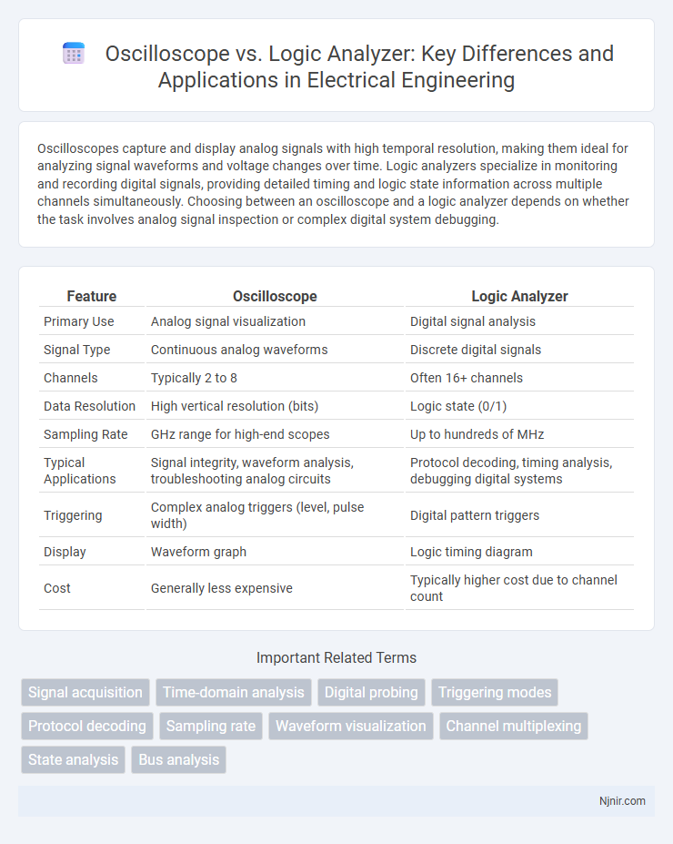
| Feature | Oscilloscope | Logic Analyzer |
|---|---|---|
| Primary Use | Analog signal visualization | Digital signal analysis |
| Signal Type | Continuous analog waveforms | Discrete digital signals |
| Channels | Typically 2 to 8 | Often 16+ channels |
| Data Resolution | High vertical resolution (bits) | Logic state (0/1) |
| Sampling Rate | GHz range for high-end scopes | Up to hundreds of MHz |
| Typical Applications | Signal integrity, waveform analysis, troubleshooting analog circuits | Protocol decoding, timing analysis, debugging digital systems |
| Triggering | Complex analog triggers (level, pulse width) | Digital pattern triggers |
| Display | Waveform graph | Logic timing diagram |
| Cost | Generally less expensive | Typically higher cost due to channel count |
Introduction to Oscilloscopes and Logic Analyzers
Oscilloscopes measure and visualize analog voltage signals over time, crucial for analyzing waveform shapes, frequencies, and voltage levels in circuits. Logic analyzers capture and display digital signals, focusing on timing and logical state transitions across multiple channels simultaneously. Both instruments complement each other in diagnosing and debugging mixed-signal electronic systems.
Core Functions and Purpose
Oscilloscopes provide detailed analog signal visualization by plotting voltage over time, making them essential for analyzing waveform characteristics such as amplitude, frequency, and distortion. Logic analyzers specialize in capturing and displaying digital signals across multiple channels simultaneously, enabling precise timing analysis and protocol decoding in complex digital circuits. Core functions of oscilloscopes center on analog signal integrity, whereas logic analyzers focus on digital data capture and state analysis.
Signal Types Measured
Oscilloscopes primarily measure analog signals by displaying voltage changes over time, allowing detailed analysis of waveform characteristics such as amplitude, frequency, and noise. Logic analyzers capture and analyze digital signals, focusing on the timing and logic states of multiple channels to troubleshoot complex digital circuits. Understanding the signal type--continuous analog versus discrete digital--is crucial when selecting between an oscilloscope and a logic analyzer for accurate data acquisition.
Key Features and Technical Specifications
Oscilloscopes provide high-resolution analog waveform visualization with bandwidths ranging from a few MHz to several GHz, featuring sample rates up to multiple GS/s and memory depths supporting detailed signal analysis. Logic analyzers excel in capturing and decoding digital signals across numerous channels, often supporting hundreds of inputs with sophisticated triggering and protocol analysis capabilities optimized for digital system debugging. Key technical distinctions include oscilloscopes' precise voltage measurement and time-based waveform display versus logic analyzers' focus on timing relationships and state analysis of digital circuits.
Ease of Use and User Interface
Oscilloscopes feature intuitive analog-style controls and graphical waveform displays, making them easier for beginners to quickly understand signal behavior. Logic analyzers offer complex multi-channel data views and timing analysis but typically require more setup and familiarity with digital protocols. User interfaces on oscilloscopes emphasize real-time signal visualization, while logic analyzers prioritize detailed digital state decoding and trigger configuration, impacting ease of use depending on the application focus.
Bandwidth and Sampling Rate Comparison
Oscilloscopes typically offer bandwidths ranging from a few MHz up to several GHz, enabling detailed analysis of high-frequency analog signals, while logic analyzers generally provide lower bandwidths suited for capturing digital signal transitions. Sampling rates in oscilloscopes can reach multiple GSa/s (gigasamples per second) to accurately reconstruct analog waveforms, whereas logic analyzers emphasize deep memory and parallel sampling of multiple channels at lower sample rates, often in the range of hundreds of MSa/s (megasamples per second). The choice between an oscilloscope and logic analyzer depends on the need for either high-bandwidth analog signal fidelity or comprehensive digital timing analysis across numerous channels.
Debugging: Analog vs Digital Signals
Oscilloscopes excel at debugging analog signals by providing real-time voltage waveform visualization with high time resolution, essential for detecting signal distortions and noise. Logic analyzers specialize in capturing and analyzing digital signals by sampling multiple channels simultaneously and decoding complex protocols to identify timing issues and logical errors. For mixed-signal debugging, combining an oscilloscope with a logic analyzer enables comprehensive analysis of both analog waveforms and digital logic states.
Data Visualization and Analysis Capabilities
Oscilloscopes excel in visualizing analog signal waveforms with high temporal resolution, making them ideal for detailed voltage-time analysis and transient event detection. Logic analyzers specialize in capturing and decoding digital signals across multiple channels, offering protocol analysis and timing correlation for complex digital systems. Both instruments provide complementary data visualization and analysis capabilities, with oscilloscopes emphasizing waveform clarity and logic analyzers delivering multi-channel digital timing insights.
Common Applications in Electrical Engineering
Oscilloscopes are commonly used for analyzing analog signals, measuring voltage levels, and observing waveforms in circuit debugging and signal integrity testing. Logic analyzers excel in capturing and analyzing digital signals, timing relationships, and state transitions within complex digital systems such as microprocessors and communication buses. Electrical engineers rely on oscilloscopes for real-time analog signal visualization and on logic analyzers for in-depth digital protocol analysis and timing verification.
Choosing the Right Instrument for Your Project
Choosing the right instrument between an oscilloscope and a logic analyzer depends on the specific needs of your project, such as signal type and analysis complexity. Oscilloscopes excel at capturing and visualizing analog signals with high bandwidth, providing detailed waveform analysis for tasks like voltage measurements and transient detection. Logic analyzers are better suited for digital system debugging, capturing multiple digital channels simultaneously and decoding communication protocols to identify timing issues and logic states.
Signal acquisition
Oscilloscopes capture analog signal waveforms with high temporal resolution while logic analyzers record multiple digital logic states simultaneously for comprehensive signal acquisition and timing analysis.
Time-domain analysis
Oscilloscopes provide high-resolution time-domain voltage waveforms for analog signal analysis while logic analyzers capture and interpret digital signal timing and state transitions across multiple channels.
Digital probing
A logic analyzer excels in digital probing by capturing and analyzing multiple digital signals simultaneously, whereas an oscilloscope provides detailed waveform visualization for fewer signals with high timing accuracy.
Triggering modes
Oscilloscopes offer edge and pulse width triggering for analog signals, while logic analyzers provide complex pattern and state-based triggering to capture digital logic events efficiently.
Protocol decoding
Oscilloscopes provide detailed analog waveform analysis with limited protocol decoding capabilities, whereas logic analyzers excel in capturing and decoding complex digital communication protocols for precise timing and state analysis.
Sampling rate
Oscilloscopes typically offer sampling rates from 1 GS/s to 100 GS/s for high-resolution waveform capture, while logic analyzers provide lower sampling rates around 100 MS/s to 1 GS/s optimized for digital signal timing analysis.
Waveform visualization
Oscilloscopes provide detailed analog waveform visualization with high time resolution, while logic analyzers focus on digital signal timing and state transitions across multiple channels.
Channel multiplexing
Oscilloscopes typically use fewer channels with time-division multiplexing for analog signals, whereas logic analyzers provide extensive channel multiplexing to capture and analyze multiple digital signals simultaneously.
State analysis
Logic analyzers excel in state analysis by capturing and interpreting digital signal states over time, whereas oscilloscopes primarily visualize analog waveforms without specialized state decoding features.
Bus analysis
Logic analyzers provide comprehensive bus analysis by capturing and decoding multiple digital signals simultaneously, whereas oscilloscopes primarily visualize electrical waveforms with limited multi-channel decoding capabilities.
Oscilloscope vs Logic Analyzer Infographic