In electrical engineering, a series circuit has components connected end-to-end, resulting in a single path for current flow, where the total resistance is the sum of individual resistances, causing the current to remain constant throughout the circuit. Conversely, a parallel circuit features components connected across common points, providing multiple paths for current, which decreases the total resistance and ensures the voltage across each component is the same. Understanding these differences is crucial for designing efficient electrical systems with desired current and voltage characteristics.
Table of Comparison
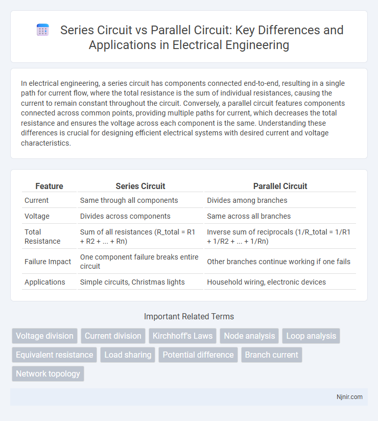
| Feature | Series Circuit | Parallel Circuit |
|---|---|---|
| Current | Same through all components | Divides among branches |
| Voltage | Divides across components | Same across all branches |
| Total Resistance | Sum of all resistances (R_total = R1 + R2 + ... + Rn) | Inverse sum of reciprocals (1/R_total = 1/R1 + 1/R2 + ... + 1/Rn) |
| Failure Impact | One component failure breaks entire circuit | Other branches continue working if one fails |
| Applications | Simple circuits, Christmas lights | Household wiring, electronic devices |
Introduction to Series and Parallel Circuits
Series circuits connect components end-to-end, allowing current to flow through a single path, whereas parallel circuits link components across multiple paths, enabling independent current flow through each branch. Voltage in a series circuit divides among components, while in a parallel circuit, voltage remains consistent across all branches. Understanding these fundamental differences is essential for designing electrical systems with desired current and voltage characteristics.
Fundamental Differences Between Series and Parallel Circuits
Series circuits have components connected end-to-end, resulting in a single current path where the total resistance equals the sum of individual resistances, causing voltage to divide across components. Parallel circuits feature components connected across the same two points, offering multiple current paths and causing the total resistance to decrease, calculated using the reciprocal formula 1/R_total = 1/R_1 + 1/R_2 + ... + 1/R_n. Voltage remains constant across each parallel branch while the current divides according to individual branch resistances, highlighting the fundamental operational differences between series and parallel configurations.
Voltage Distribution in Series vs Parallel Circuits
In a series circuit, voltage divides across components proportionally to their resistance, meaning the total voltage equals the sum of voltages across each element. In contrast, a parallel circuit maintains the same voltage across all branches, with current splitting according to each branch's resistance. Understanding this voltage distribution is critical for designing electrical systems to ensure components receive appropriate voltage levels without damage.
Current Flow Analysis: Series vs Parallel
In a series circuit, current flows sequentially through each component, maintaining a constant current throughout the entire circuit, which means the same current passes through all elements. In contrast, a parallel circuit divides the current among multiple branches, with each branch carrying a portion of the total current based on its resistance, resulting in different current values across parallel paths. Understanding these current flow differences is crucial for designing electrical systems that require precise control of current distribution and component performance.
Resistance Calculation in Series and Parallel Setups
In a series circuit, the total resistance is the sum of all individual resistances, calculated as R_total = R1 + R2 + ... + Rn, causing the current to remain consistent throughout the circuit. In contrast, a parallel circuit's total resistance is found using the reciprocal formula 1/R_total = 1/R1 + 1/R2 + ... + 1/Rn, which results in a lower overall resistance than any single resistor in the setup. Understanding these calculation methods is crucial for designing circuits with desired current and voltage characteristics in electrical engineering.
Power Distribution and Efficiency
Series circuits deliver consistent current through each component but suffer from increased total resistance, reducing overall power efficiency in complex systems. Parallel circuits distribute voltage evenly across branches, allowing independent component operation and minimizing power loss, leading to higher efficiency in power distribution networks. Efficient power systems predominantly utilize parallel configurations to maintain stable voltage and optimize energy consumption across multiple devices.
Advantages of Series Circuits
Series circuits offer the advantage of simplicity in design and ease of construction, making them ideal for basic electrical applications. Their current is constant throughout all components, enabling straightforward analysis and predictable performance. This uniform current flow also ensures that voltage drops are easily calculated, simplifying troubleshooting and component selection.
Benefits of Parallel Circuits
Parallel circuits offer improved reliability by allowing each component to operate independently, meaning if one branch fails, the others continue functioning without interruption. They provide consistent voltage across all devices, ensuring optimal performance and reducing the risk of damage caused by voltage drops. This configuration enhances electrical efficiency and safety in household wiring and electronic systems.
Common Applications in Electrical Engineering
Series circuits are commonly used in applications like string lights and fuse protection systems where current consistency is crucial. Parallel circuits dominate in household wiring and automotive electrical systems to ensure constant voltage and independent operation of devices. Electrical engineers prefer parallel configurations in data centers and power distribution networks to enhance reliability and maintain system stability.
Selecting the Right Circuit Configuration
Selecting the right circuit configuration depends on the application's requirements for voltage, current, and reliability. Series circuits provide a single path for current, useful for applications needing uniform current flow, but failure in one component disrupts the entire circuit. Parallel circuits offer multiple paths for current, ensuring consistent voltage across components and higher reliability, making them ideal for devices requiring stable voltage and independent operation.
Voltage division
In a series circuit, voltage divides proportionally across each component based on resistance, whereas in a parallel circuit, all components experience the same voltage regardless of individual resistance.
Current division
In a series circuit, current remains constant through all components, whereas in a parallel circuit, current divides among branches inversely proportional to their resistances.
Kirchhoff's Laws
Kirchhoff's Voltage Law states that in a series circuit the sum of voltage drops equals the total voltage, while Kirchhoff's Current Law indicates that in a parallel circuit the total current divides among branches according to their resistances.
Node analysis
Node analysis in parallel circuits simplifies voltage calculations at each node by treating nodes as voltage reference points, whereas in series circuits, node voltages change sequentially along the single path, making node analysis less straightforward.
Loop analysis
Loop analysis in series circuits involves calculating current through a single path causing identical current flow, while in parallel circuits it involves multiple loops with different currents requiring Kirchhoff's Voltage Law to solve each loop for voltage and current distribution.
Equivalent resistance
Equivalent resistance in a series circuit is the sum of all individual resistances, whereas in a parallel circuit, the reciprocal of the equivalent resistance equals the sum of the reciprocals of each individual resistance.
Load sharing
In a series circuit, load sharing is sequential with current constant but voltage divided, whereas in a parallel circuit, load sharing allows each component to receive full voltage while current divides among branches.
Potential difference
In a series circuit, the potential difference divides across each component, while in a parallel circuit, the potential difference remains the same across all branches.
Branch current
In a series circuit, the branch current remains constant across all components, whereas in a parallel circuit, the branch current divides according to the resistance of each parallel branch.
Network topology
In network topology, series circuits connect components sequentially along a single path, while parallel circuits arrange components on multiple branches, allowing independent current flow through each branch.
series circuit vs parallel circuit Infographic