Power factor quantifies the efficiency of electrical power usage by comparing real power to apparent power, expressed as a cosine of the phase angle between voltage and current waveforms. A smaller phase angle indicates a higher power factor, meaning more efficient energy consumption with less reactive power in the system. Managing the phase angle through power factor correction techniques reduces energy losses and improves overall system performance in electrical engineering applications.
Table of Comparison
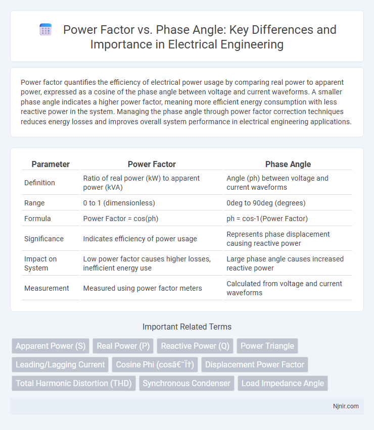
| Parameter | Power Factor | Phase Angle |
|---|---|---|
| Definition | Ratio of real power (kW) to apparent power (kVA) | Angle (ph) between voltage and current waveforms |
| Range | 0 to 1 (dimensionless) | 0deg to 90deg (degrees) |
| Formula | Power Factor = cos(ph) | ph = cos-1(Power Factor) |
| Significance | Indicates efficiency of power usage | Represents phase displacement causing reactive power |
| Impact on System | Low power factor causes higher losses, inefficient energy use | Large phase angle causes increased reactive power |
| Measurement | Measured using power factor meters | Calculated from voltage and current waveforms |
Introduction to Power Factor and Phase Angle
Power factor measures the efficiency of electrical power usage by quantifying the ratio of real power to apparent power in an AC circuit. Phase angle represents the angular difference between voltage and current waveforms, directly influencing power factor values. A smaller phase angle corresponds to a higher power factor, indicating more effective power consumption and reduced energy losses.
Understanding Power Factor in Electrical Systems
Power factor in electrical systems represents the ratio of real power flowing to the load to the apparent power in the circuit, indicating efficiency in power usage. It is mathematically defined as the cosine of the phase angle between voltage and current waveforms, where a smaller phase angle signifies a higher power factor and reduced reactive power. Improving power factor minimizes energy losses, enhances voltage stability, and reduces electricity costs in industrial and commercial power systems.
The Concept of Phase Angle in AC Circuits
Phase angle in AC circuits represents the time difference between the voltage and current waveforms, measured in degrees, which directly influences power factor. A phase angle of zero degrees means voltage and current are perfectly in phase, resulting in a power factor of 1, indicating maximum efficiency. As the phase angle increases, the power factor decreases, causing more reactive power and less real power transfer in the circuit.
Mathematical Relationship Between Power Factor and Phase Angle
Power factor is mathematically defined as the cosine of the phase angle (ph) between voltage and current waveforms in an AC circuit, expressed as PF = cos(ph). This relationship indicates that as the phase angle increases from 0deg to 90deg, the power factor decreases from 1 to 0, signifying a reduction in usable real power. Understanding this trigonometric connection is essential for optimizing electrical system efficiency and minimizing reactive power losses.
Effects of Phase Angle on Power Factor
Phase angle directly impacts power factor by determining the ratio of real power to apparent power in an AC circuit. As the phase angle between voltage and current increases, the power factor decreases, indicating higher reactive power and reduced efficiency. A smaller phase angle results in a power factor closer to unity, minimizing energy losses and improving system performance.
Power Factor: Leading vs Lagging
Power factor measures the efficiency of electrical power usage, expressed as the cosine of the phase angle between voltage and current waveforms. A leading power factor occurs when the current waveform leads the voltage, typically caused by capacitive loads, whereas a lagging power factor happens when the current lags behind the voltage, commonly due to inductive loads. Maintaining an optimal power factor, close to unity, reduces energy losses and improves system stability in AC power networks.
Impact of Power Factor and Phase Angle on System Efficiency
Power factor, defined as the cosine of the phase angle between voltage and current, directly impacts system efficiency by influencing real power delivery and reducing energy losses. Low power factor, characterized by a large phase angle, causes increased current flow, leading to higher I2R losses in electrical systems and reduced capacity of power equipment. Improving power factor minimizes phase angle, optimizes active power utilization, and enhances overall electrical system performance and cost-effectiveness.
Methods to Measure Power Factor and Phase Angle
Power factor and phase angle are critical parameters in assessing electrical system efficiency; measuring power factor typically involves using power analyzers or a digital clamp meter with power factor functionality, which calculates the ratio of real power to apparent power. Phase angle measurement is commonly performed using an oscilloscope or a power quality analyzer that captures the time difference between voltage and current waveforms, converting it into an angular value. Advanced methods integrate both measurements in smart meters and power monitors to provide real-time data for optimizing load performance and detecting power quality issues.
Techniques for Improving Power Factor
Improving power factor involves techniques such as installing capacitor banks to provide leading reactive power, which compensates for lagging inductive loads and reduces phase angle between voltage and current. Synchronous condensers are also employed for dynamic power factor correction by adjusting excitation to control reactive power flow. Advanced methods include using power factor correction devices like active filters that mitigate harmonics and maintain optimal phase alignment, enhancing overall system efficiency.
Practical Applications: Power Factor and Phase Angle in Industrial Settings
Power factor in industrial settings directly impacts energy efficiency by minimizing reactive power, which reduces electricity costs and enhances equipment lifespan. Phase angle, representing the difference between voltage and current waveforms, helps diagnose power quality issues and optimize motor performance. Understanding the relationship between power factor and phase angle enables engineers to implement corrective measures such as capacitor banks or synchronous condensers to improve overall system reliability and reduce demand charges.
Apparent Power (S)
Apparent Power (S) quantifies the product of voltage and current magnitudes in an AC circuit, representing the vector sum of active power (P) and reactive power (Q) and directly relating to the power factor through the cosine of the phase angle between voltage and current.
Real Power (P)
Real Power (P) equals Apparent Power (S) multiplied by the cosine of the phase angle (ph), making Power Factor (PF) = cos(ph) a critical measure for efficient energy utilization.
Reactive Power (Q)
Reactive Power (Q) directly influences the phase angle between voltage and current, where a larger phase angle corresponds to a lower power factor, indicating increased reactive power in the system.
Power Triangle
The Power Triangle illustrates the relationship between real power (kW), reactive power (kVAR), and apparent power (kVA), where the power factor is the cosine of the phase angle between voltage and current.
Leading/Lagging Current
Leading current occurs when the power factor is greater than zero and the phase angle is negative, indicating current leads voltage, while lagging current occurs when the power factor is less than zero and the phase angle is positive, indicating current lags voltage.
Cosine Phi (cos φ)
Cosine Phi (cos ph) represents the power factor, quantifying the phase angle difference between voltage and current to indicate the efficiency of electrical power usage.
Displacement Power Factor
Displacement Power Factor measures the cosine of the phase angle difference between voltage and current waveforms, indicating the efficiency of real power usage in AC circuits.
Total Harmonic Distortion (THD)
Total Harmonic Distortion (THD) significantly impacts power factor by distorting the phase angle between voltage and current, leading to reduced electrical efficiency and increased losses in power systems.
Synchronous Condenser
A synchronous condenser improves power factor by adjusting the phase angle between voltage and current, enabling reactive power compensation and voltage stabilization in electrical power systems.
Load Impedance Angle
Load impedance angle directly influences power factor by determining the phase difference between voltage and current, where a smaller impedance angle results in a higher power factor and improved energy efficiency.
Power Factor vs Phase Angle Infographic