An RLC circuit includes a resistor (R), inductor (L), and capacitor (C), allowing it to exhibit resonance and frequency selectivity, unlike an RC circuit which only contains resistors and capacitors. The presence of the inductor in the RLC circuit introduces inductive reactance, resulting in complex impedance that varies with frequency, whereas the RC circuit's impedance depends solely on capacitive reactance and resistance. These differences make RLC circuits essential for applications like tuning and filtering, while RC circuits are commonly used for simpler timing and filtering tasks.
Table of Comparison
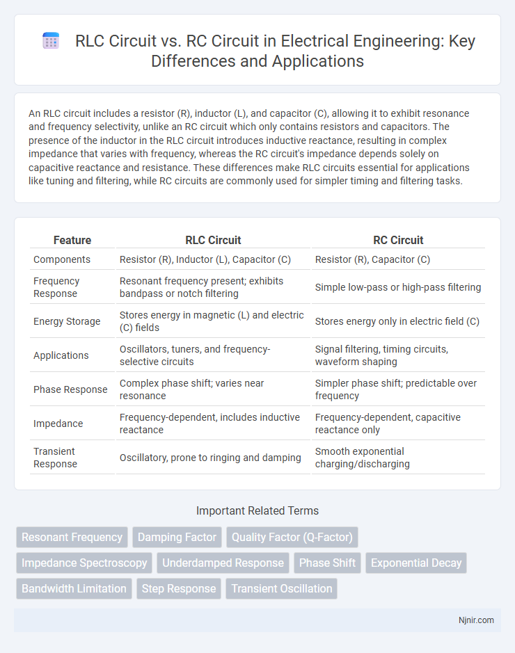
| Feature | RLC Circuit | RC Circuit |
|---|---|---|
| Components | Resistor (R), Inductor (L), Capacitor (C) | Resistor (R), Capacitor (C) |
| Frequency Response | Resonant frequency present; exhibits bandpass or notch filtering | Simple low-pass or high-pass filtering |
| Energy Storage | Stores energy in magnetic (L) and electric (C) fields | Stores energy only in electric field (C) |
| Applications | Oscillators, tuners, and frequency-selective circuits | Signal filtering, timing circuits, waveform shaping |
| Phase Response | Complex phase shift; varies near resonance | Simpler phase shift; predictable over frequency |
| Impedance | Frequency-dependent, includes inductive reactance | Frequency-dependent, capacitive reactance only |
| Transient Response | Oscillatory, prone to ringing and damping | Smooth exponential charging/discharging |
Overview of RLC and RC Circuits
RLC circuits contain a resistor (R), inductor (L), and capacitor (C), enabling them to exhibit oscillatory behavior and resonance at a specific frequency, critical for tuning applications in radio and signal processing. RC circuits consist of resistors and capacitors, primarily used for filtering, timing, and waveform shaping due to their ability to store and release energy, affecting signal phase and amplitude. The presence of the inductor in RLC circuits introduces inductive reactance, differentiating their impedance characteristics from the purely capacitive and resistive nature of RC circuits.
Fundamental Components Comparison
An RLC circuit consists of a resistor (R), inductor (L), and capacitor (C) connected in series or parallel, enabling resonance and frequency-selective filtering, unlike an RC circuit that only includes a resistor and capacitor. The inductor in the RLC circuit introduces inductive reactance, affecting impedance and phase angle, while the RC circuit relies solely on capacitive reactance and resistance for its frequency response. Fundamental difference lies in energy storage: the capacitor stores energy electrically, the inductor stores energy magnetically, and the resistor dissipates energy as heat in both circuits.
Circuit Configurations and Diagrams
An RLC circuit includes a resistor (R), inductor (L), and capacitor (C) connected in series or parallel, forming a resonant circuit capable of oscillation and frequency selection, whereas an RC circuit contains only a resistor and capacitor arranged to filter or delay signals without inductive properties. Circuit diagrams of RLC circuits depict the inductor symbol alongside resistor and capacitor symbols, highlighting their combined reactive effects, while RC circuit diagrams omit the inductor, representing simpler low-pass or high-pass filter configurations. The inductor in RLC circuits introduces inductive reactance, affecting impedance and phase angle, contrasting with the purely capacitive reactance in RC circuits that influences signal integration or differentiation.
Resonance in RLC vs RC Circuits
Resonance in RLC circuits occurs when inductive reactance equals capacitive reactance, resulting in maximum current flow and minimal impedance at the resonant frequency. In contrast, RC circuits do not exhibit true resonance because they lack an inductor to create inductive reactance; instead, they display a frequency-dependent phase shift and amplitude attenuation. The presence of the inductor in RLC circuits allows for energy exchange between magnetic and electric fields, enabling sharp resonance peaks utilized in filters, oscillators, and tuning applications.
Frequency Response Analysis
An RLC circuit exhibits a frequency response characterized by resonance at a specific frequency where inductive and capacitive reactances cancel, resulting in a peak in voltage or current amplitude. In contrast, an RC circuit displays frequency-dependent attenuation without resonance, acting primarily as a low-pass or high-pass filter based on the configuration. The presence of the inductor in the RLC circuit introduces a sharper bandwidth and higher quality factor (Q), making it suitable for selective frequency applications compared to the simpler frequency roll-off in RC circuits.
Damping and Oscillation Effects
RLC circuits exhibit underdamped, critically damped, or overdamped responses based on resistor, inductor, and capacitor values, leading to oscillatory or non-oscillatory transient behaviors, while RC circuits primarily display exponential charging or discharging without oscillations due to the absence of inductive energy storage. The presence of the inductor in RLC circuits introduces oscillations characterized by resonance frequency and damping factor, influencing the amplitude and frequency of transient oscillations. In contrast, RC circuits have a single time constant governing their damping, resulting in a monotonic voltage or current decay without oscillatory dynamics.
Applications in Electrical Engineering
RLC circuits are widely used in electrical engineering for designing oscillators, tuning circuits, and filters due to their ability to resonate at specific frequencies, making them ideal for radio transmitters and receivers. In contrast, RC circuits are primarily applied in timing devices, such as clocks and pulse generators, as well as in signal filtering to remove high-frequency noise. The selection between RLC and RC circuits depends on the need for frequency selectivity and transient response characteristics in applications like communication systems and analog signal processing.
Power Loss and Efficiency
RLC circuits experience power loss primarily due to the resistance component causing heat dissipation, which reduces overall efficiency compared to ideal LC circuits. RC circuits typically exhibit higher power loss as the resistor continuously consumes energy, leading to lower efficiency in signal filtering applications. Efficient design in RLC circuits balances inductance, capacitance, and resistance to minimize power dissipation and optimize performance in AC signal processing.
Impedance Characteristics
The impedance of an RLC circuit varies with frequency due to the combined effects of resistance (R), inductive reactance (XL = 2pfL), and capacitive reactance (XC = 1/(2pfC)), producing a resonant frequency where impedance is minimized or maximized. In contrast, the RC circuit impedance consists only of resistance and capacitive reactance, resulting in a frequency-dependent impedance that decreases with increasing frequency but lacks a resonant peak. Understanding these impedance characteristics is crucial for designing filters, oscillators, and frequency-dependent circuit applications.
Practical Design Considerations
RLC circuits incorporate resistors, inductors, and capacitors, offering enhanced control over frequency response and transient behavior compared to simpler RC circuits, which include only resistors and capacitors. Practical design considerations for RLC circuits include managing inductive reactance, minimizing energy losses in inductors, and addressing resonance effects, essential for applications like tuning and filtering. RC circuits prioritize simplicity and cost-effectiveness, making them suitable for basic filtering and timing, but they lack the frequency selectivity and damping control inherent in RLC designs.
Resonant Frequency
The resonant frequency of an RLC circuit depends on the inductance (L) and capacitance (C) values as \( f_0 = \frac{1}{2\pi\sqrt{LC}} \), whereas an RC circuit does not exhibit resonance due to the absence of an inductive element.
Damping Factor
The damping factor in an RLC circuit depends on resistance, inductance, and capacitance, whereas in an RC circuit, it solely depends on resistance and capacitance, resulting in different transient response behaviors.
Quality Factor (Q-Factor)
The RLC circuit features a higher quality factor (Q-Factor) due to its inductive and capacitive reactances balancing at resonance, whereas the RC circuit exhibits a lower Q-Factor because it lacks inductance, resulting in greater energy dissipation.
Impedance Spectroscopy
Impedance spectroscopy reveals that RLC circuits exhibit frequency-dependent resonance peaks due to inductive reactance, while RC circuits show a smoother impedance variation dominated by capacitive reactance and resistance.
Underdamped Response
The underdamped response in an RLC circuit features oscillatory voltage and current with gradually decreasing amplitude due to the presence of inductance and capacitance, unlike the RC circuit where the response is non-oscillatory and exponentially decays.
Phase Shift
The RLC circuit exhibits a variable phase shift dependent on frequency and resonance conditions, whereas the RC circuit consistently produces a phase shift limited to 90 degrees where current either leads or lags the voltage.
Exponential Decay
The exponential decay in an RLC circuit differs from an RC circuit due to the presence of inductance, causing damped oscillations, while the RC circuit exhibits a simple exponential voltage decay without oscillations.
Bandwidth Limitation
RLC circuits typically offer narrower bandwidth limitations due to their resonance properties, while RC circuits provide broader bandwidth with less selectivity in frequency response.
Step Response
The step response of an RLC circuit exhibits oscillatory behavior due to the inductor's energy storage, while an RC circuit shows a smooth exponential rise or decay determined solely by resistor-capacitor interactions.
Transient Oscillation
RLC circuits exhibit transient oscillations due to energy exchange between the inductor and capacitor, unlike RC circuits which produce only exponential transient responses without oscillations.
RLC Circuit vs RC Circuit Infographic