Sine waves provide smooth, continuous oscillations that are fundamental in AC power systems due to their efficient energy transmission and minimal harmonic distortion. Square waves, characterized by abrupt transitions between high and low states, are commonly used in digital electronics for clock signals but introduce significant harmonic content, leading to potential interference and power losses. Understanding the differences between sine and square waves is crucial for optimizing signal integrity and system performance in electrical engineering applications.
Table of Comparison
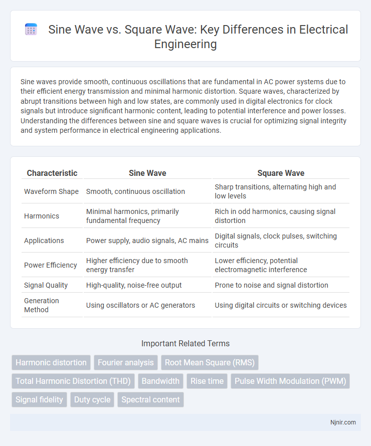
| Characteristic | Sine Wave | Square Wave |
|---|---|---|
| Waveform Shape | Smooth, continuous oscillation | Sharp transitions, alternating high and low levels |
| Harmonics | Minimal harmonics, primarily fundamental frequency | Rich in odd harmonics, causing signal distortion |
| Applications | Power supply, audio signals, AC mains | Digital signals, clock pulses, switching circuits |
| Power Efficiency | Higher efficiency due to smooth energy transfer | Lower efficiency, potential electromagnetic interference |
| Signal Quality | High-quality, noise-free output | Prone to noise and signal distortion |
| Generation Method | Using oscillators or AC generators | Using digital circuits or switching devices |
Introduction to Sine and Square Waves
Sine waves represent smooth, periodic oscillations characterized by a continuous and symmetrical waveform fundamental to AC electricity and signal processing. Square waves consist of abrupt transitions between high and low levels, producing a waveform with distinct harmonic content used in digital electronics and timing applications. Both waveforms serve crucial roles in electronics, with sine waves exemplifying pure frequency signals and square waves enabling binary switching and clock pulses.
Fundamental Properties and Characteristics
Sine waves have smooth periodic oscillations characterized by a single fundamental frequency with harmonics decreasing exponentially in amplitude, resulting in pure tonal quality ideal for audio and signal processing. Square waves consist of abrupt transitions between high and low states, producing a fundamental frequency accompanied by strong odd harmonics that generate a rich, buzzy sound useful in digital electronics and waveform synthesis. The sinusoidal waveform's continuous nature contrasts with the square wave's discontinuities, affecting bandwidth, harmonic content, and energy distribution across the frequency spectrum.
Generation Methods of Sine and Square Waves
Sine waves are typically generated using analog oscillators such as LC circuits or Wien bridge oscillators, relying on continuous-time sinusoidal feedback to produce smooth, periodic waveforms. Digital methods for sine wave generation include direct digital synthesis (DDS), which uses a phase accumulator and lookup tables to create precise, high-frequency sine signals. Square waves are commonly generated by digital circuits like flip-flops or microcontrollers, which toggle output states between high and low levels, or by using a comparator with a triangle or sine waveform to produce sharp transitions.
Frequency Spectrum and Harmonic Content
A sine wave features a pure frequency spectrum with a single fundamental frequency and no harmonics, resulting in a smooth and continuous waveform. In contrast, a square wave contains a fundamental frequency plus a series of odd harmonics with decreasing amplitudes, creating its characteristic sharp transitions. The presence of these harmonics in square waves contributes to a richer harmonic content and a more complex frequency spectrum compared to sine waves.
Applications in Electrical Engineering
Sine waves are fundamental in AC power systems and signal processing due to their smooth periodic oscillations, facilitating efficient energy transmission and minimal harmonic distortion. Square waves find critical use in digital electronics and switching circuits, providing clear binary signals essential for microcontrollers and timing devices. Both waveforms are integral in designing oscillators, filters, and communication systems, with their distinct spectral properties tailoring them to specific engineering applications.
Signal Integrity and Noise Considerations
Sine waves offer superior signal integrity due to their smooth, continuous waveform, minimizing harmonic distortion and electromagnetic interference, which reduces noise in communication systems. Square waves consist of abrupt transitions and rich harmonics, increasing the likelihood of signal reflections and crosstalk that degrade signal quality. Choosing sine waves can enhance noise immunity while square waves require careful filtering and impedance matching to maintain signal integrity in high-speed digital circuits.
Power Efficiency and Losses
Sine waves exhibit higher power efficiency in AC systems due to their smooth, continuous oscillations which minimize harmonic distortion and reduce energy losses in electrical components. Square waves contain abrupt transitions causing significant harmonic content, leading to increased core losses, heat generation, and reduced overall power efficiency in transformers and motors. Power electronic devices operating with sine waves experience lower electromagnetic interference and improved thermal performance compared to those driven by square waves.
Impact on Electronic Components
Sine waves produce smooth, continuous oscillations that minimize harmonic distortion, reducing stress on electronic components and enhancing their longevity. Square waves contain sharp transitions and numerous high-frequency harmonics, which can induce excessive electromagnetic interference and heat, potentially damaging sensitive circuitry. Choosing between sine and square waves significantly affects component durability, noise levels, and overall system performance in electronic applications.
Measurement and Analysis Techniques
Measurement and analysis of sine waves typically involve using oscilloscopes and spectrum analyzers to accurately assess amplitude, frequency, and harmonic distortion due to their smooth, periodic nature. Square wave analysis requires high-speed sampling instruments to capture rapid transitions and duty cycle variations, often utilizing Fourier transform techniques to decompose the waveform into its fundamental frequency and odd harmonics. Precision in time-domain sampling and frequency-domain spectral analysis is crucial for differentiating signal integrity and distortion characteristics between sine and square waves.
Choosing Between Sine and Square Waves
Choosing between sine and square waves depends on the application requirements; sine waves provide smooth, continuous oscillations ideal for audio signals and AC power due to their low harmonic distortion. Square waves, characterized by abrupt transitions and high harmonic content, are preferable in digital circuits and switching power supplies where sharp on/off signals enhance performance. Understanding the spectral properties and power efficiency of each waveform guides optimal selection for signal processing and electronic design tasks.
Harmonic distortion
Sine waves produce minimal harmonic distortion with a single fundamental frequency, while square waves contain a series of odd harmonics causing significant harmonic distortion and spectral complexity.
Fourier analysis
Fourier analysis reveals that a sine wave consists of a single fundamental frequency, while a square wave comprises a fundamental frequency plus an infinite series of odd harmonics with decreasing amplitude.
Root Mean Square (RMS)
The RMS value of a sine wave is approximately 0.707 times its peak amplitude, while the RMS value of a square wave equals its peak amplitude, making square waves deliver higher effective power for the same peak voltage.
Total Harmonic Distortion (THD)
Square waves exhibit significantly higher Total Harmonic Distortion (THD) compared to sine waves due to their sharp transitions causing numerous harmonic frequencies.
Bandwidth
Square waves require significantly wider bandwidth than sine waves due to their harmonic-rich frequency spectrum.
Rise time
Square waves have significantly faster rise times compared to sine waves due to their abrupt voltage transitions and harmonic richness.
Pulse Width Modulation (PWM)
Pulse Width Modulation (PWM) uses square waves with varying duty cycles to simulate the power delivery of sine waves for efficient motor control and signal processing applications.
Signal fidelity
Sine waves offer higher signal fidelity due to their smooth, continuous oscillations, while square waves introduce harmonics and distortion that reduce signal purity.
Duty cycle
The duty cycle of a square wave defines the percentage of one period in which the signal is high, directly impacting power delivery, while a sine wave's continuous oscillation lacks a duty cycle parameter.
Spectral content
A sine wave contains a single fundamental frequency with no harmonics, while a square wave consists of a fundamental frequency plus an infinite series of odd harmonics with amplitudes decreasing inversely with harmonic number.
Sine wave vs Square wave Infographic