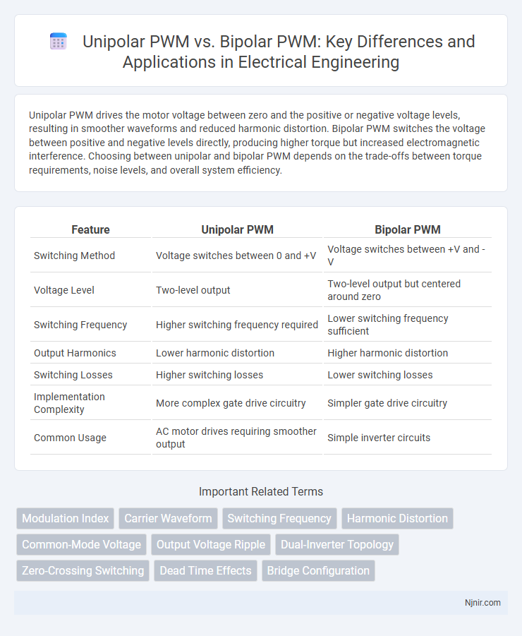
Unipolar PWM drives the motor voltage between zero and the positive or negative voltage levels, resulting in smoother waveforms and reduced harmonic distortion. Bipolar PWM switches the voltage between positive and negative levels directly, producing higher torque but increased electromagnetic interference. Choosing between unipolar and bipolar PWM depends on the trade-offs between torque requirements, noise levels, and overall system efficiency.
Table of Comparison
| Feature | Unipolar PWM | Bipolar PWM |
|---|---|---|
| Switching Method | Voltage switches between 0 and +V | Voltage switches between +V and -V |
| Voltage Level | Two-level output | Two-level output but centered around zero |
| Switching Frequency | Higher switching frequency required | Lower switching frequency sufficient |
| Output Harmonics | Lower harmonic distortion | Higher harmonic distortion |
| Switching Losses | Higher switching losses | Lower switching losses |
| Implementation Complexity | More complex gate drive circuitry | Simpler gate drive circuitry |
| Common Usage | AC motor drives requiring smoother output | Simple inverter circuits |
Introduction to PWM Techniques in Electrical Engineering
Unipolar PWM generates output voltage pulses by switching the signal between zero and a positive or negative reference voltage, resulting in lower harmonic distortion and reduced switching losses compared to bipolar PWM. Bipolar PWM alternates the output voltage between positive and negative reference voltages directly, causing higher switching frequency stress on power devices due to rapid polarity changes. Both techniques are fundamental in controlling inverter output voltage and optimizing power conversion efficiency in electrical engineering applications.
Overview of Unipolar and Bipolar PWM Modulation
Unipolar PWM modulation switches the output voltage between zero and positive or negative voltage levels, producing less harmonic distortion and lower electromagnetic interference (EMI). Bipolar PWM modulation alternates the output voltage symmetrically between positive and negative voltage levels, resulting in higher switching losses but a simpler control scheme. Unipolar PWM is commonly used in applications requiring efficient power conversion and reduced filter size, while bipolar PWM offers robust performance in motor drive systems.
Unipolar PWM: Working Principle and Characteristics
Unipolar PWM operates by switching the voltage between zero and a positive or negative voltage level, resulting in a waveform that changes polarity only relative to the zero voltage line. This method reduces harmonic distortion and switching losses compared to bipolar PWM, where the voltage switches directly between positive and negative levels. The unipolar approach enhances efficiency and is commonly used in motor drives and inverter circuits for smoother output voltage control.
Bipolar PWM: Operation and Features
Bipolar PWM operates by switching the output voltage polarity between positive and negative relative to the reference point, creating a waveform that alternates between +Vdc and -Vdc. This method reduces harmonic distortion and improves the quality of the output signal, resulting in lower total harmonic distortion (THD) compared to unipolar PWM. Bipolar PWM is commonly used in applications requiring precise motor control and efficient power conversion due to its simpler modulation scheme and enhanced electromagnetic compatibility.
Key Differences Between Unipolar and Bipolar PWM
Unipolar PWM switches the voltage polarity on one side of the load while keeping the other side at a constant reference, resulting in lower harmonic distortion and reduced electromagnetic interference. Bipolar PWM alternates the voltage polarity across both terminals of the load, producing higher voltage amplitude but with increased switching losses and greater EMI. The key differences lie in waveform symmetry, switching frequency, and efficiency, with unipolar PWM favored for its smoother output and bipolar PWM chosen for applications requiring higher power output.
Impact on Harmonic Distortion and Waveform Quality
Unipolar PWM generates lower harmonic distortion by switching voltage between zero and positive or negative levels, resulting in cleaner waveforms with reduced high-frequency harmonics. Bipolar PWM alternates the output voltage between positive and negative levels directly, producing higher switching frequency harmonics that can degrade waveform quality. Choosing unipolar PWM enhances overall efficiency and reduces electromagnetic interference due to improved harmonic profiles.
Efficiency Considerations in Power Conversion
Unipolar PWM improves efficiency in power conversion by reducing switching losses since the voltage across the load switches between zero and a positive or negative level, minimizing the power dissipated during transitions. Bipolar PWM, switching the voltage directly between positive and negative levels, tends to increase switching losses due to higher voltage swings but offers better output waveform quality. In high-frequency applications, unipolar PWM's reduced switching losses contribute to better overall system efficiency and lower thermal stress on components.
Switching Losses and Thermal Performance
Unipolar PWM typically exhibits lower switching losses compared to bipolar PWM due to its single-ended voltage switching, resulting in reduced stress on power devices. This lower switching loss translates to improved thermal performance, allowing for more efficient heat dissipation and cooler operation of the inverter components. Bipolar PWM, involving voltage swings between positive and negative rails, generally generates higher switching losses and increased thermal stress, necessitating more robust cooling solutions.
Application Areas: Where to Use Unipolar vs Bipolar PWM
Unipolar PWM is widely used in applications requiring lower electromagnetic interference and smoother motor operation, such as in small DC motors, LED dimming, and low-power inverters. Bipolar PWM finds its strength in high-power applications like industrial motor drives, induction heating, and advanced power converters, where faster switching and higher efficiency are critical. Choosing between unipolar and bipolar PWM depends on the specific requirements for power level, efficiency, noise sensitivity, and switching speed in the target application.
Practical Selection Guidelines for PWM Techniques
Unipolar PWM offers lower switching losses and reduced electromagnetic interference, making it ideal for applications requiring high efficiency and noise-sensitive environments. Bipolar PWM provides better harmonic performance and simpler implementation, suitable for systems prioritizing waveform quality over switching losses. Select unipolar PWM for high-frequency drives and inverters seeking optimal efficiency, while bipolar PWM is preferable in low-frequency or cost-sensitive applications.
Modulation Index
Unipolar PWM offers a higher effective modulation index and lower harmonic distortion compared to bipolar PWM, resulting in improved voltage utilization and smoother output waveform in inverter applications.
Carrier Waveform
Unipolar PWM uses a single polarity carrier waveform that switches between zero and positive voltage levels, enhancing switching efficiency, while bipolar PWM employs a carrier waveform oscillating symmetrically between positive and negative voltages, resulting in higher harmonic content.
Switching Frequency
Unipolar PWM typically allows higher switching frequencies than bipolar PWM due to its reduced voltage stress and lower switching losses.
Harmonic Distortion
Unipolar PWM significantly reduces harmonic distortion by producing lower noise and smoother output waveforms compared to bipolar PWM, which generates higher harmonic content due to its rapid voltage switching between positive and negative states.
Common-Mode Voltage
Unipolar PWM generates lower common-mode voltage compared to bipolar PWM, reducing electromagnetic interference and improving motor insulation longevity.
Output Voltage Ripple
Unipolar PWM produces lower output voltage ripple compared to bipolar PWM due to its switching pattern that reduces switching losses and voltage fluctuations.
Dual-Inverter Topology
Dual-inverter topology with unipolar PWM offers reduced switching losses and lower electromagnetic interference compared to bipolar PWM, enhancing motor drive efficiency and performance.
Zero-Crossing Switching
Unipolar PWM offers reduced switching losses and lower electromagnetic interference by employing Zero-Crossing Switching that alternates between zero and positive or negative voltages, whereas bipolar PWM switches directly between positive and negative voltages, increasing switching stress and harmonic distortion.
Dead Time Effects
Unipolar PWM reduces dead time effects by minimizing switching losses and voltage distortion compared to bipolar PWM, which suffers greater dead time-induced harmonic distortion and reduced efficiency.
Bridge Configuration
Unipolar PWM in bridge configurations switches voltage between zero and positive or negative rails for reduced switching losses, while bipolar PWM alternates output voltage directly between positive and negative rails, offering simpler control but higher harmonic distortion.
unipolar PWM vs bipolar PWM Infographic