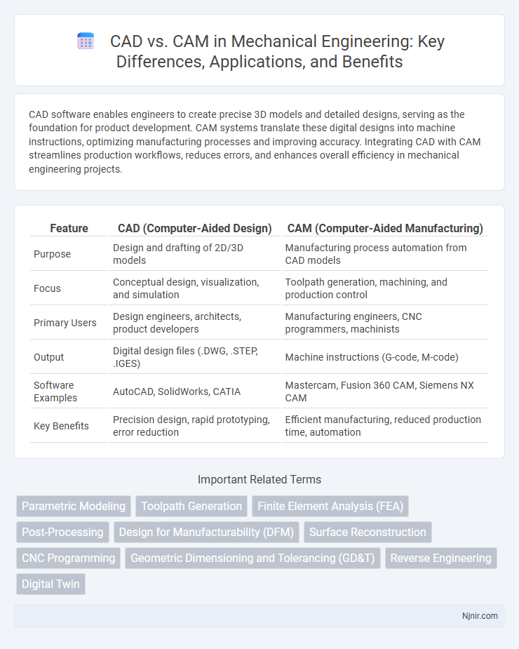
CAD software enables engineers to create precise 3D models and detailed designs, serving as the foundation for product development. CAM systems translate these digital designs into machine instructions, optimizing manufacturing processes and improving accuracy. Integrating CAD with CAM streamlines production workflows, reduces errors, and enhances overall efficiency in mechanical engineering projects.
Table of Comparison
| Feature | CAD (Computer-Aided Design) | CAM (Computer-Aided Manufacturing) |
|---|---|---|
| Purpose | Design and drafting of 2D/3D models | Manufacturing process automation from CAD models |
| Focus | Conceptual design, visualization, and simulation | Toolpath generation, machining, and production control |
| Primary Users | Design engineers, architects, product developers | Manufacturing engineers, CNC programmers, machinists |
| Output | Digital design files (.DWG, .STEP, .IGES) | Machine instructions (G-code, M-code) |
| Software Examples | AutoCAD, SolidWorks, CATIA | Mastercam, Fusion 360 CAM, Siemens NX CAM |
| Key Benefits | Precision design, rapid prototyping, error reduction | Efficient manufacturing, reduced production time, automation |
Introduction to CAD and CAM in Mechanical Engineering
Computer-Aided Design (CAD) and Computer-Aided Manufacturing (CAM) are essential tools in mechanical engineering that enhance the design and production processes. CAD software allows engineers to create precise 2D and 3D models of mechanical components, optimizing geometry and material usage for improved functionality and efficiency. CAM integrates these digital designs directly into manufacturing workflows, enabling automated machining, reduced errors, and faster production cycles for complex mechanical parts.
Core Differences Between CAD and CAM
CAD (Computer-Aided Design) primarily focuses on the creation, modification, and optimization of a digital model or blueprint for products, allowing engineers to visualize and simulate designs with precision. CAM (Computer-Aided Manufacturing) uses the CAD model to control machinery and automate manufacturing processes, translating designs into physical parts through toolpath generation and machine instructions. The core difference lies in CAD being a design tool for developing product specifications, while CAM is a production tool that manages and directs the manufacturing workflow.
Key Features and Functionalities of CAD
CAD (Computer-Aided Design) software excels in creating detailed 2D and 3D models with precision, offering tools for drafting, dimensioning, and design validation that streamline product development. It provides extensive features like parametric modeling, simulation, and automated rendering to enhance design accuracy and visualization. CAD integrates seamlessly with other engineering tools, enabling efficient design modifications and collaboration across teams.
Major Benefits of Using CAM Software
CAM software significantly enhances manufacturing efficiency by automating machine tool programming and reducing manual errors. It optimizes production workflows through precise toolpath generation, leading to faster machining times and improved material utilization. Integration with CAD models allows seamless transition from design to production, minimizing lead times and boosting overall manufacturing accuracy.
Integration of CAD and CAM in Manufacturing
The integration of CAD (Computer-Aided Design) and CAM (Computer-Aided Manufacturing) in manufacturing streamlines the entire production process by enabling seamless transfer of design data directly to manufacturing equipment. This unified approach reduces errors, shortens production cycles, and enhances precision in fabricating complex parts. Advanced CAD/CAM software systems facilitate real-time design modifications and optimize tool paths, improving overall efficiency and product quality.
Common Applications of CAD and CAM
CAD is commonly used in architectural design, automotive engineering, and product prototyping for creating detailed 2D and 3D models. CAM is widely applied in manufacturing processes such as CNC machining, 3D printing, and automated assembly to convert CAD designs into physical products. Both systems integrate closely in industries like aerospace and consumer electronics to streamline design-to-production workflows.
Impact on Product Design and Prototyping
CAD (Computer-Aided Design) enhances product design by enabling precise digital models, facilitating complex geometries, and allowing rapid modifications, which significantly reduces design errors and accelerates innovation. CAM (Computer-Aided Manufacturing) directly impacts prototyping by translating CAD designs into automated machining instructions, improving production speed and accuracy while minimizing material waste. The integration of CAD and CAM streamlines the transition from design to physical prototype, optimizing development cycles and enabling quicker iteration for product refinement.
Challenges in Implementing CAD and CAM Solutions
Implementing CAD and CAM solutions often faces challenges such as high initial costs for software and hardware, requiring significant investment from companies. Integration difficulties arise due to compatibility issues between existing systems and new CAD/CAM technologies, leading to workflow disruptions. Additionally, the need for skilled personnel to operate and maintain these advanced tools presents a continuous training and recruitment challenge for organizations.
Future Trends in CAD and CAM Technologies
Future trends in CAD and CAM technologies emphasize integration with artificial intelligence and machine learning to enhance design automation and precision manufacturing. Cloud-based CAD/CAM platforms enable real-time collaboration and data accessibility, significantly improving workflow efficiency. Advances in additive manufacturing and generative design algorithms are reshaping product development cycles, reducing time-to-market and material waste.
Choosing the Right CAD and CAM Tools for Your Needs
Selecting the right CAD and CAM tools hinges on understanding the specific requirements of your project, such as complexity, material, and production volume. CAD software like AutoCAD, SolidWorks, and Fusion 360 excels in precision design and 3D modeling, while CAM solutions such as Mastercam and Fusion 360 CAM focus on efficient toolpath generation and machine control. Evaluating software compatibility, ease of use, and integration capabilities ensures an optimal workflow from design through manufacturing.
Parametric Modeling
Parametric modeling in CAD enables dynamic design modifications by using constraints and parameters, enhancing precision and efficiency in CAM-driven manufacturing processes.
Toolpath Generation
CAD software designs models while CAM software generates precise toolpaths to control CNC machine movements for manufacturing.
Finite Element Analysis (FEA)
Finite Element Analysis (FEA) integrates with CAD software to simulate and optimize designs virtually, while CAM utilizes FEA data to enhance manufacturing precision and reduce production errors.
Post-Processing
Post-processing in CAD vs CAM involves converting CAD-designed models into machine-readable code through CAM software to enable precise manufacturing and efficient CNC machining.
Design for Manufacturability (DFM)
Design for Manufacturability (DFM) in CAD enhances product designs by optimizing geometry and tolerances for efficient CAM-driven manufacturing processes, reducing production costs and time.
Surface Reconstruction
Surface reconstruction in CAD focuses on creating precise digital models from geometric data, while CAM utilizes these reconstructed surfaces to generate accurate toolpaths for manufacturing.
CNC Programming
CAD software designs precise 3D models that serve as the foundation for CAM systems to generate optimized CNC programming codes, ensuring accurate and efficient machining processes.
Geometric Dimensioning and Tolerancing (GD&T)
Geometric Dimensioning and Tolerancing (GD&T) integrates with CAD for precise design specifications and transfers these controls into CAM systems to ensure accurate manufacturing and quality inspection.
Reverse Engineering
Reverse engineering integrates CAD software to digitally reconstruct complex designs from existing physical objects, enabling precise modifications and manufacturing through CAM systems.
Digital Twin
Digital Twin technology integrates CAD designs with CAM processes to create real-time, virtual models that optimize manufacturing efficiency and predictive maintenance.
CAD vs CAM Infographic